2-2
SM 338 Equipment Manual
(4) J31069-D401-U1-A0-7618
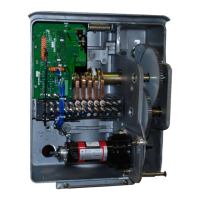
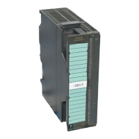
2.1 Layout
The SM 338 i s installed in a compact, plastic housing. This housing is
mounted on the rail of your programmable controller.
The two plug connectors on the back connect the module to the P bus.
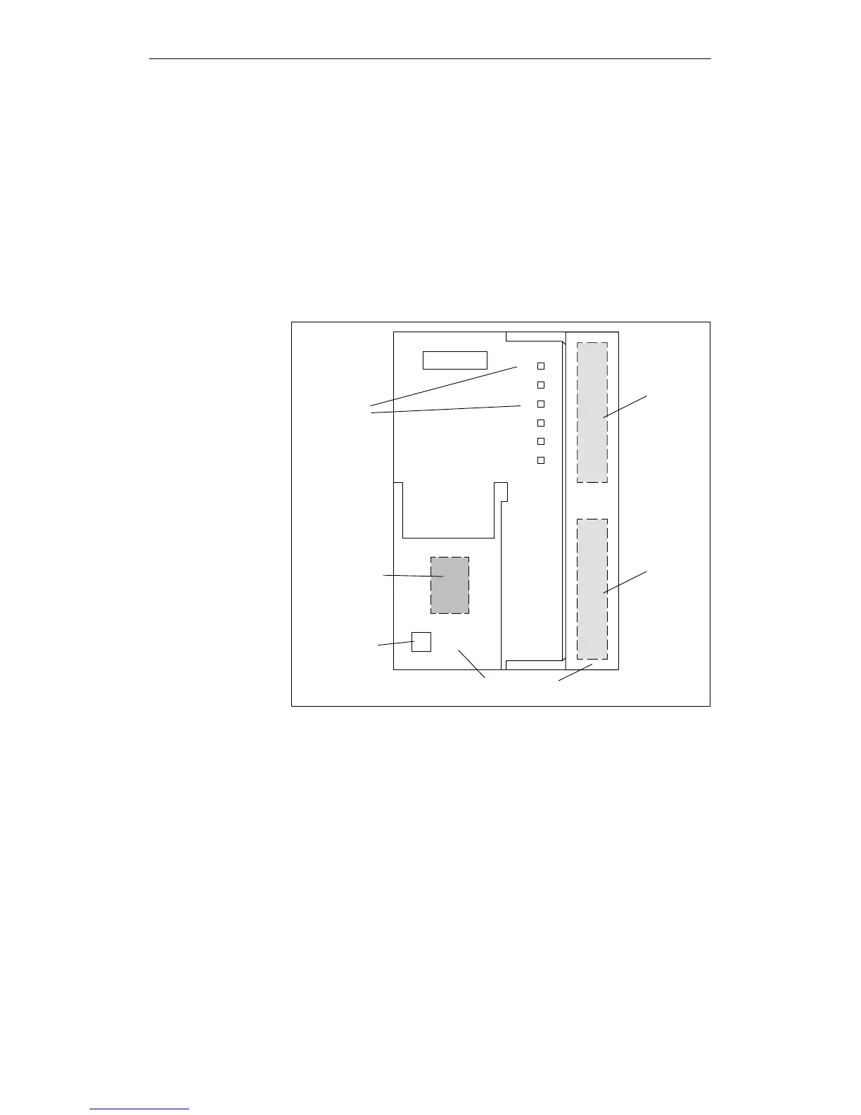
All other connection and indicator elements are located on the front of the
module. Figure 2-1 shows the location of these elements.
SF
LED indi-
cators
External
supply volt-
age (24 V)
X
Slot number
Covering flaps
Sensors
2+4
Sensors
1+3
DC
Figure 2-1 Front view of the module
The back
The front
The SM
 Loading...