3-4
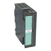
SM 338 Equipment Manual
(4) J31069-D401-U1-A0-7618
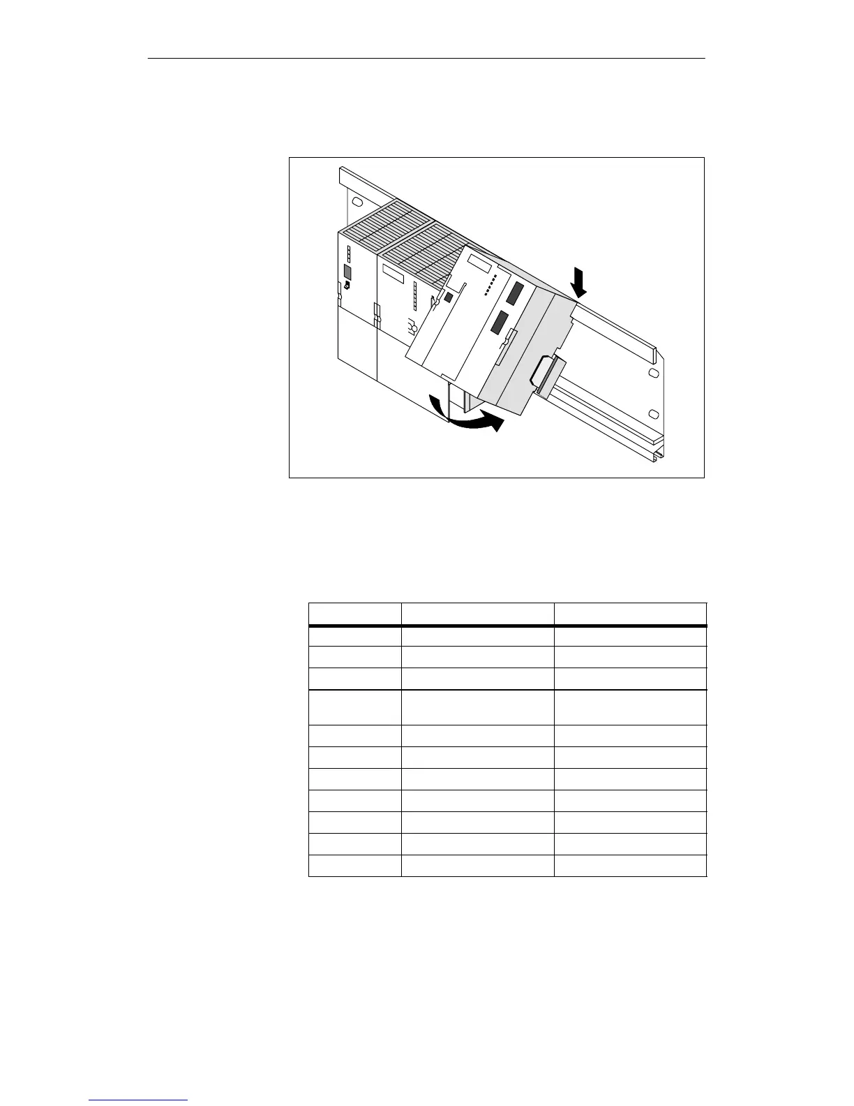
6. Hook i n (1) the SM 338 on the top of t he rail, and swing down (2).
(1)
(2)
7. Tighten both modules with screws (turning moment for screwdriver:
80 to 110 Ncm).
8. Assign the SM 338 a slot number as shown in table 3-2.
Table 3-2 Slot numbers for S7 modules
Slot Number
Module Remarks
1 Power supply (PS) -
2 Central processing unit (CPU) -
3 Interface module (IM) -
4 1st signal module To the right, next to the CPU
or IM
5 2nd signal module -
6 3rd signal module -
7 4th signal module -
8 5th signal module -
9 6th signal module -
10 7th signal module -
11 8th signal module -
In
 Loading...