4-5
SM 338 Equipment Manual
(4) J31069-D401-U1-A0-7618
Two bytes each are used to assign the eight counters to the four sensors and
to specify their measuring points.
Table 4-2 shows the applicable bytes for each sensor.
Table 4-2 Bytes for counter assignment
Sensor Number
Bytes
1 2and3
2 5and6
3 8and9
4 11 and 12
Measuring point 1
Measuring point 2
Measuring point 3
Measuring point 4
0000 Nocounter assigned
0001 Counter 1 assigned
0010 Counter 2 assigned
0011 Counter 3 assigned
..
..
..
0111 Counter 7 assigned
1000 Counter 8 assigned
1001 Nocounter assigned*
..
..
..
1111 Nocounter assigned*
70
Byte n
70
Byte (n+1)
Note
The counter assignments marked with an * are illegal and will trigger the
diagnosis message “wrong parameters on the module”.
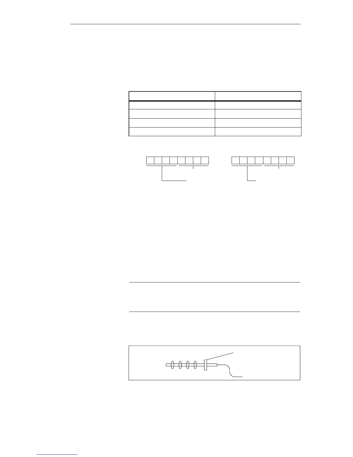
Counting of the measuring points of a sensor always begins with the sensor
electronics.
Measuring point
Electronics
3421
Figure 4-2 Example of the measuring points of a sensor
Sensor-related
counter assign-
ment
D
 Loading...