6 General Repair
6B Hand Controls Repair
6 -24
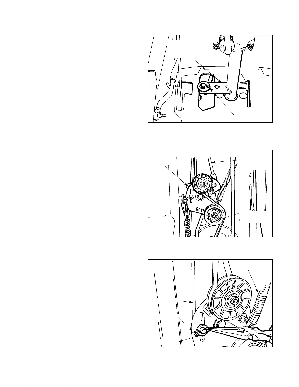
Figure B–15. Front Shift Rod/Ground Speed
Control Lever Assembly Attachment
Front & Rear Shift Rod Service -
Hydro-Gear 216 Models
1. Remove battery from unit to provide access to front
shift lever rod assembly at base of shift lever assem-
bly (Figure B–15)
2. Remove cotter pin that secures front shift lever rod to
shift lever arm, and set spacer aside for reuse when
reassembling rod.
Figure B–16. Idler Arm Assembly Area - Underside
Of Unit
3. Safely elevate and support unit (mower deck re-
moved) for working access to idler arm assembly
area and related shift linkage parts (Figure B–16)
Figure B–17. Remove Cotter Pin
4. See Figure B–17. After noting assembly position of
front and rear clutch rods (to ensure proper assembly
when reassembling parts), remove cotter pin and
washer from front clutch rod.
5. See Figure B–17. Disengage the drive spring from
the underside of the frame to release tension on the
idler arm assembly, and remove.
Cotter Pin
Ground Speed
Control Lever
Assembly Arm
Idler Arm
Assembly
Front Shift
Rod
Rear Shift
Rod
Cotter Pin
Washer
Clutch Rod
Drive Spring
 Loading...