27
3. On gear models, see figure 26. Loosen the nut (A)
that secures the front control rod (B) to the rear con-
trol bar (C). Control rod must move freely. Move the
ground speed control lever into the neutral gate and
tighten nut (A) securely to 17 ft. lbs.
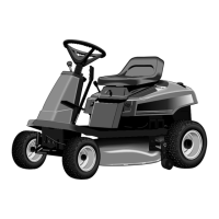
On hydro models, see figure 27. Loosen the nut (A)
that secures the front control rod (B) to the rear con-
trol rod (C). Control rod must move freely. Move the
ground speed control lever into the neutral gate and
tighten nut (A) securely to 17 ft. lbs. Perform the fol-
lowing Return-To-Neutral Adjustment procedure.
4. Check operation of rider for any movement with shift
lever in neutral gate.
RETURN-TO-NEUTRAL ADJUSTMENT
- HYDRO MODELS
Perform this adjustment if the ground speed control lever
does not return to the neutral gate from forward when the
clutch/brake pedal is fully depressed. Make sure the
hydro control rod (B, figure 27) is lubricated and does not
bind in the carrier frame hole.
1. Make sure the Neutral Adjustment is correct as
described in the preceeding procedure.
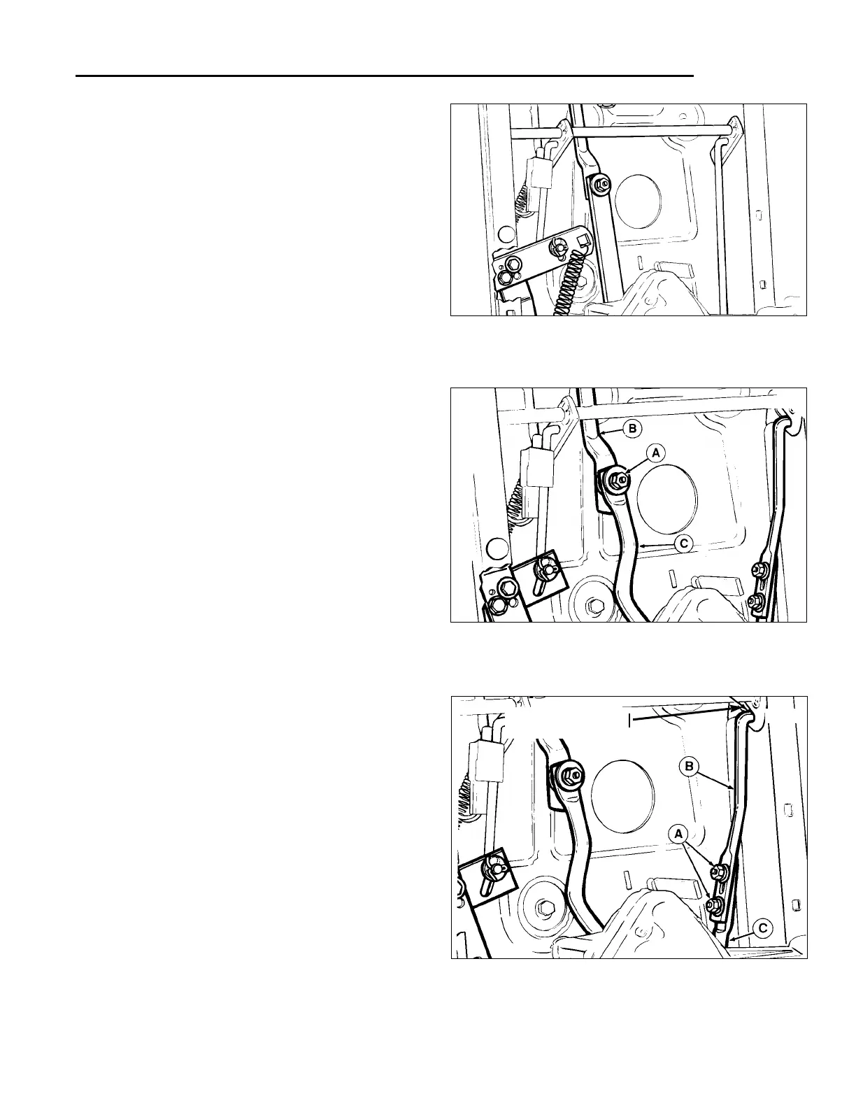
2. See figure 28. Loosen the two nuts (A) that secure
the front return-to-neutral rod (B) to the rear rod (C).
Return-to-neutral rod must move freely.
3. Place the ground speed control lever in the full for-
ward position.
4. Move the front return-to-neutral rod all the way rear-
ward in the slot to shorten the length of the assem-
bled rods (B & C). Tighten the two nuts (A).
5. Start the riderand check the return-to-neutral opera-
tion of the ground speed control lever.
IDLER PULLEY ADJUSTMENT
- HYDRO MODELS
Perform the following adjustment if the rider drive belt
does not completely declutch when the clutch/brake
pedal is depressed.
(continued on page 28)
Adjustments
*2510
*2425
Figure 26. Neutral Adjustment - Gear Models
A. Nut C. Rear Control Bar
B. Front Control Rod
Figure 27. Neutral Adjustment - Hydro Models
A. Nut C. Rear Control Rod
B. Front Control Rod
NEUTRAL ADJUSTMENT
Perform the following adjustment if the rider travels for-
ward or backward with the ground speed control lever
positioned in the neutral gate.
1. Position the rider on flat, level ground and start the
engine.
2. Position shift lever so that the rider has no forward or
reverse movement. Shift lever may not necessarily
be in the the neutral gate. Shut off the engine. Do not
depress the clutch/brake pedal or move the ground
speed control lever.
Figure 28. Return-To-Neutral Adjustment
- Hydro Models
A. Nut B. Front Return-To-Neutral Rod
C. Rear Return-To- Neutral Rod
*2425
Move rod (B) to rear
of slot
 Loading...