28
Section 7. (Continued)
Lawn Tractors with HydroGear 318-0500/322-0500/322-0650 Transaxle (With Foot Control)
When making adjustment, keep hands, hair,
clothing, and tools away from rotating belts.
Grasp cam lever at base to keep hand several
inches below belt rotating around idler pulley
assembly. Careless or improper attention may
result in serious injury.
WARNING
If the tractor creeps forward or backward with the
engine running and both travel pedals released,
perform the following adjustment:
NOTE: For Hydro-Gear 0500 transmission part
number 1713761 see Figure 7-7. For the Hydro-Gear
0650 transmission part number 1715765 see Figure
7—8. An identification decal is attached to the
transmission case.
1. Block the front wheels and raise the rear of the
tractor off the ground with a suitable hoist or
floor jack. Install jackstands underneath the
transaxle.
2. Start the engine and release the parking brake
while keeping seat switch depressed.
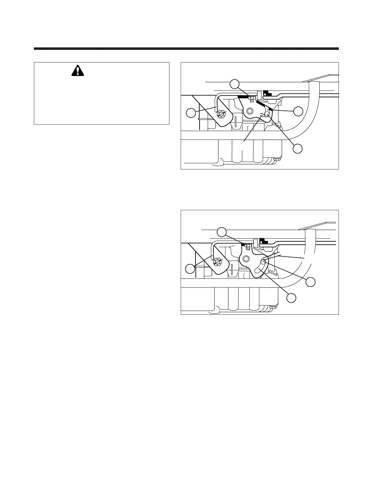
3. Loosen the nut (A) securing the neutral adjust-
ment rod (B). Move the rod until neutral is found,
then retighten the nut.
NOTE: The stop pin (D, Figure 7-7 and 7-8) should
be positioned near the end of the cam slot when the
front pedal edge is 1/4" above the frame (pedal fully
depressed). If it is not, proceed to the Forward
Speed Adjustment procedure. The stop pin should
not “bottom out” in the cam slot. Increasing the
distance between the end of the cam slot and the
stop pin will increase reverse speed and decrease
forward speed.
B
A
C
D
Figure 7-7 Neutral Adjustment - Hydro-Gear 0500, Part Number
1713761
A. Nut C. Cam Slot
B. Neutral Adjustment Rod D. Stop Pin
Viewed from right side of tractor with rear
wheel removed and foot pedal fully depressed.
Gap
Figure 7-8. Neutral Adjustment - Hydro-Gear 0650 Part Number
1715765.
(Linkage removed for clarity)
A. Nut C. Cam Slot
B. Neutral Adjustment Rod D. Stop Pin
Viewed from right side of tractor with rear wheel removed and
foot pedal fully depressed.
D
C
B
A
Gap
 Loading...