29
If the unit does not reach top speed with the forward
direction pedal fully depressed, perform the follow-
ing adjustment with the engine off and PTO disen-
gaged.
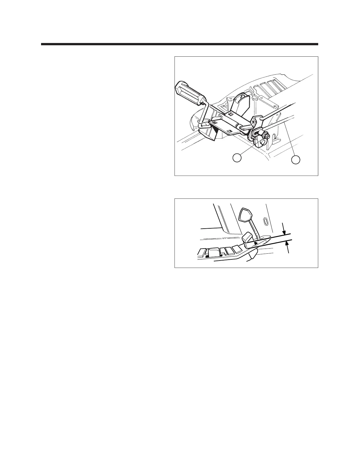
1. See Figure 7-9. Loosen the nut (A) securing the
control rod to the hydro control lever.
2. Position the pedal so the distance between the
frame and bottom edge of the pedal is 1-3/4" as
shown in Figure 7-10.
3. With pedal in this position, tighten the nut (A,
Figure 7-9).
4. The stop pin (D, Figure 7-7 and 7-8 previous
page) should be positioned at the end of the cam
slot as shown when the front pedal edge is 1/4"
above the frame (pedal fully depressed). If it is
not, loosen nut (A, Figure 7-9) and adjust pedal as
necessary, then retighten nut.
NOTE: The stop pin (D, Figure 7-7 and 7-8) should
be positioned near the end of the cam slot when the
front pedal edge is 1/4" above the frame (pedal fully
depressed). The stop pin should not “bottom out” in
the cam slot. Increasing the distance between the
end of the cam slot and the stop pin will increase
reverse speed and decrease forward speed.
Section 7. (Continued)
Lawn Tractors with HydroGear 318-0500/322-0500/322-0650 Transaxle (With Foot Control)
A
B
Figure 7-9 Forward Speed Adjustment Linkage - Hydro Models
A. Nut B. Control Rod
Figure 7-10 Forward Speed Adjustment - Hydro
1 3/4"
Unit pictured from above with frame removed.
 Loading...