EasyManuals Logo
Home>Smartgen>Controller>HGM7100N Series

Smartgen HGM7100N Series User Manual

Smartgen HGM7100N Series
47 pages
To Next Page IconTo Next Page
To Previous Page IconTo Previous Page
Page #18 background imageLoading...
Page #18 background image
HGM7100N GENSET CONTROLLER USER MANUAL
HGM7100N Genset Controller 2020-09-10 Version1.2 Page 18 of 47
7 WIRINGS CONNECTION
Compared with HGM7120N, HGM7110N is missing one mains voltage three-phase input terminal.
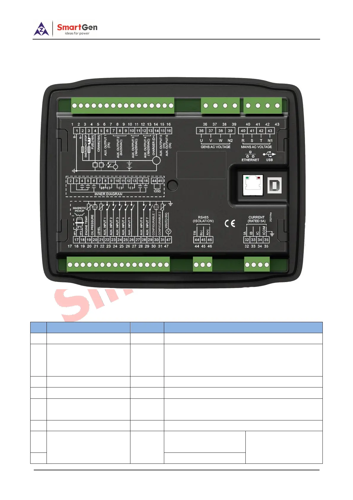
HGM7120N controller back panel is as follows:
Fig. 3 - HGM7120N Back Panel
Table 9 - Terminal Wiring Connection
No.
Function
Cable Size
Remarks
1
B-
2.5mm
2
Connected with negative of starter battery
2
B+
2.5mm
2
Connected with positive of starter battery. If wire length
is over 30m, better to double wires in parallel. Max. 20A
fuse is recommended.
3
Emergency Stop
2.5mm
2
Connect emergency stop button with B+.
4
Fuel (16A)
1.5mm
2
B+ is supplied by No.3 terminal, rated 16A.
5
Crank (16A)
1.5mm
2
B+ is supplied by No.3 terminal, rated 16A.
Connect with starting coil of starter.
6
Aux. Output 1(7A)
1.5mm
2
B+ is supplied by No.2 terminal, rated 7A.
7
Aux. Output 2(8A 250VAC)
1.5 mm
2
Normally close output,
rated 8A.
Details see Table 11
8
Relay common port

Questions and Answers:

Question and Answer IconNeed help?

Do you have a question about the Smartgen HGM7100N Series and is the answer not in the manual?

Smartgen HGM7100N Series Specifications

General IconGeneral
BrandSmartgen
ModelHGM7100N Series
CategoryController
LanguageEnglish

Related product manuals