- 44 -
7. Troubleshooting
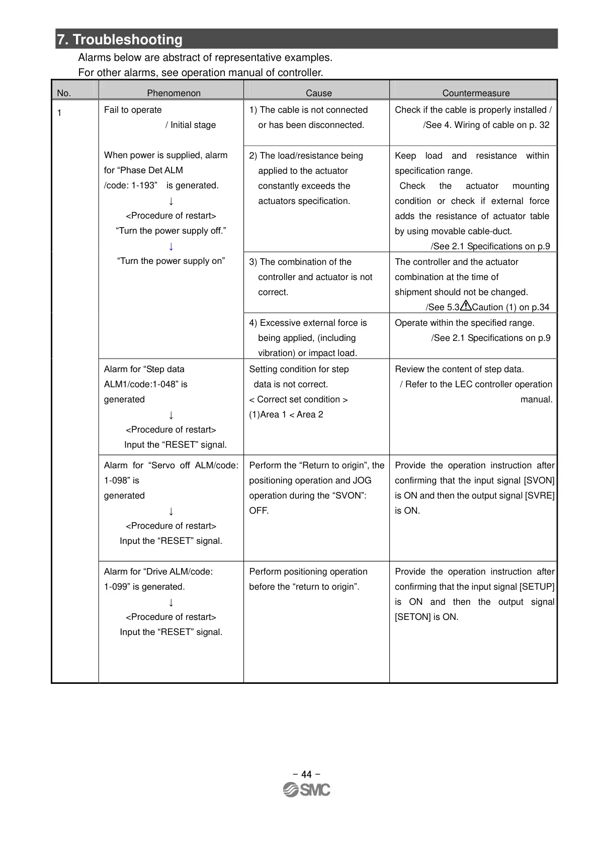
Alarms below are abstract of representative examples.
For other alarms, see operation manual of controller.
Fail to operate
/ Initial stage
When power is supplied, alarm
for “Phase Det ALM
/code: 1-193” is generated.
↓
<Procedure of restart>
“Turn the power supply off.”
↓
“Turn the power supply on”
1) The cable is not connected
or has been disconnected.
Check if the cable is properly installed /
/See 4. Wiring of cable on p. 32
2) The load/resistance being
applied to the actuator
constantly exceeds the
actuators specification.
Keep load and resistance within
specification range.
Check the actuator mounting
condition or check if external force
adds the resistance of actuator table
by using movable cable-duct.
/See 2.1 Specifications on p.9
3) The combination of the
controller and actuator is not
correct.
The controller and the actuator
combination at the time of
shipment should not be changed.
/See 5.3 Caution (1) on p.34
4) Excessive external force is
being applied, (including
vibration) or impact load.
Operate within the specified range.
/See 2.1 Specifications on p.9
Alarm for “Step data
ALM1/code:1-048” is
generated
↓
<Procedure of restart>
Input the “RESET” signal.
Setting condition for step
data is not correct.
< Correct set condition >
(1)Area 1 < Area 2
Review the content of step data.
/ Refer to the LEC controller operation
manual.
Alarm for “Servo off ALM/code:
1-098” is
generated
↓
<Procedure of restart>
Input the “RESET” signal.
Perform the “Return to origin”, the
positioning operation and JOG
operation during the “SVON”:
OFF.
Provide the operation instruction after
confirming that the input signal [SVON]
is ON and then the output signal [SVRE]
is ON.
Alarm for “Drive ALM/code:
1-099” is generated.
↓
<Procedure of restart>
Input the “RESET” signal.
Perform positioning operation
before the “return to origin”.
Provide the operation instruction after
confirming that the input signal [SETUP]
is ON and then the output signal
[SETON] is ON.
2021-05-2010:32
DW913599

 Loading...


