1-4
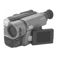
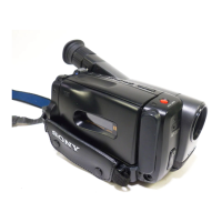
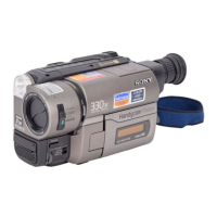
CCD-TRV128/TRV228/TRV228E/TRV328/TRV428/TRV428E
1-5. SELF-DIAGNOSIS FUNCTION
1-5-1. Self-diagnosis Function
When problems occur while the unit is operating, the self-diagnosis
function starts working, and displays on the viewfinder or Display
window what to do. This function consists of two display; self-
diagnosis display and service mode display.
Details of the self-diagnosis functions are provided in the Instruction
manual.
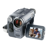
1-5-2. Self-diagnosis Display
When problems occur while the unit is operating, the counter of the
viewfinder or Display window shows a 4-digit display consisting
of an alphabet and numbers, which blinks at 3.2 Hz. This 5-character
display indicates the “repaired by:”, “block” in which the problem
occurred, and “detailed code” of the problem.
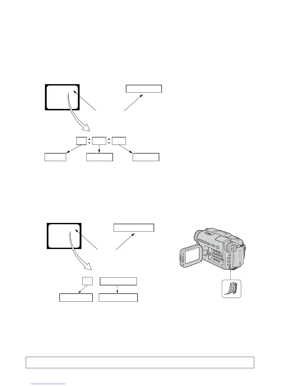
1-5-3. Service Mode Display
The service mode display shows up to six self-diagnosis codes shown in the past.
1. Display Method
While pressing the “STOP” key, set the switch from OFF to “ON”, and continue pressing the “STOP” key for 5 seconds continuously. The
service mode will be displayed, and the counter will show the backup No. and the 5-character self-diagnosis codes.
2. Switching of Backup No.
By rotating the control dial, past self-diagnosis codes will be shown in order. The backup No. in the [] indicates the order in which the
problem occurred. (If the number of problems which occurred is less than 6, only the number of problems which occurred will be shown.)
[1] : Occurred first time [3] : Occurred third time [5] : Occurred fifth time
[2] : Occurred second time [4] : Occurred fourth time [6] : Occurred the last time
3. End of Display
Turning OFF the power supply will end the service mode display.
Order of previous errors
Backup No.
Self-diagnosis Codes
C : 3 1 : 1 1
[3]
Lights up
Viewfinder
[3] C : 3 1 : 1 1
3 C : 3 1 : 11
Display window
1 1
3 1
C : 3 1 : 11
C
Repaired by:
Refer to “1-5-4. Self-diagnosis Code Table”.
Indicates the appropriate
step to be taken.
E.g.
31 ....Reload the tape.
32 ....Turn on power again.
Block
Detailed Code
Blinks at 3.2Hz
C : Corrected by customer
H : Corrected by dealer
E : Corrected by service
engineer
Viewfinder Display window
C : 3 1 : 1 1
Control Dial
Note: The “self-diagnosis display” data will not be erased (reset), when the lithium battery (CONTROL KEY BLOCK (CF-
5100): BT001) is removed.
 Loading...