16
HCD-EC50
Note on Schematic Diagram:
• All capacitors are in µF unless otherwise noted. (p: pF)
50 WV or less are not indicated except for electrolytics and
tantalums.
• All resistors are in Ω and
1
/
4
W or less unless otherwise
specified.
• f : internal component.
• 2 : nonflammable resistor.
• 5 : fusible resistor.
• C : panel designation.
• H : adjustment for repair.
• A : B+ Line.
• B : B– Line.
•Voltages are taken with a VOM (Input impedance 10 MΩ).
Voltage variations may be noted due to normal production
tolerances.
•Waveforms are taken with a oscilloscope.
Voltage variations may be noted due to normal production
tolerances.
– BD Section –
No mark: CD PLAY
– Other Section –
No mark: FM
(): TAPE PLAY
〈〉: TAPE REC
[]: CD STOP
• Circled numbers refer to waveforms.
• Signal path.
F : TUNER (FM)
f : TUNER (AM)
J : CD
d : AUX
E : PB (TAPE)
a : REC (TAPE)
•Abbreviation
AUS: Australian model
CET : East Europian and Russian models
CND : Canadian model
E3 : 240V AC area in E model
KR : Korean model
SP : Singapore model
Note on Printed Wiring Boards:
• X : parts extracted from the component side.
• Y : parts extracted from the conductor side.
• f : internal component.
• : Pattern from the side which enables seeing.
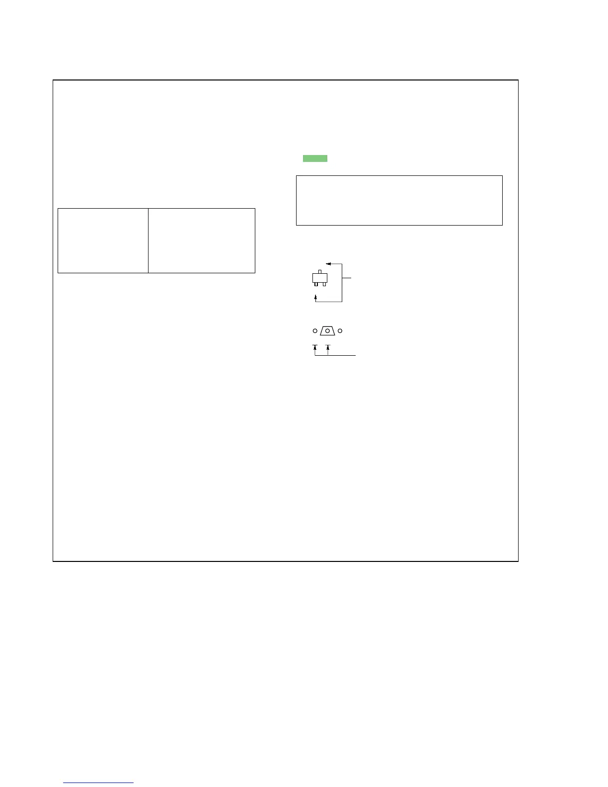
• Indication of transistor.
C
B
These are omitted.
E
Q
Note:
The components identi-
fied by mark 0 or dot-
ted line with mark 0 are
critical for safety.
Replace only with part
number specified.
Note:
Les composants identifiés
par une marque 0 sont cri-
tiques pour la sécurité.
Ne les remplacer que par une
piéce portant le numéro
spécifié.
Caution:
Pattern face side: Parts on the pattern face side seen from
(Side B) the pattern face are indicated.
Parts face side: Parts on the parts face side seen from
(Side A) the parts face are indicated.
THIS NOTE IS COMMON FOR PRINTED WIRING BOARDS AND SCHEMATIC DIAGRAMS.
(In addition to this, the necessary note is printed in each block.)
SECTION 6
DIAGRAMS
Ver. 1.3
 Loading...