HCD-F200/F500
13
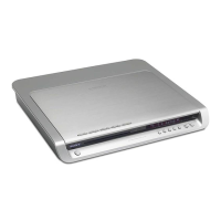
four insulator screws
insulator
insulator
insulator
insulator
connector
optical pick-up block
Note: A screw hole of this screw tends to be damaged,
so please be careful about the installation time
and the time of removal.
sheet
Note: Please spread a seat under a set
not to injure front panel assy.
– rear view –
3-5. OPTICAL PICK-UP BLOCK
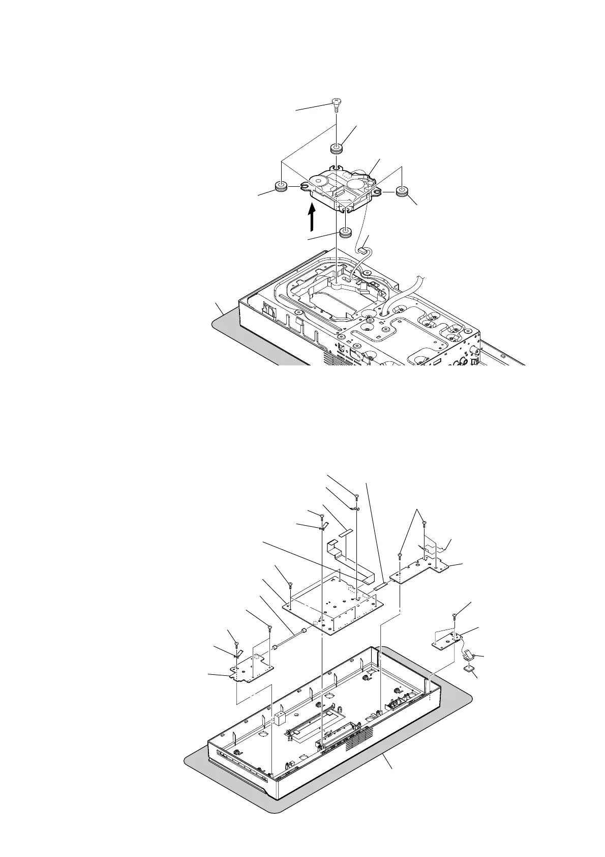
3-6. KEY-R/FL/KEY-L/USB BOARD
Note: These boards can be in any order removed.
screw (BVTP2.6)
harness
(FL board: CN808/KEY-R board: CN881)
ground plate (PWB)
ground plate (PWB)
RT
FL board
RM
USB board
wire (flat type) (7 core)
(KEY-L board: CN871/FL board: CN807)
wire (flat type) (17 core)
(CN806)
ground plate (PWB)
KEY-R board
two screws (BVTP2.6)
unweaved cloth
RI
two screws
(BVTP2.6)
RL
ground plate
(USB)
RK
gasket (USB)
screw (BVTP2.6)
screw (BVTP2.6)
RB
five screws (BVTP2.6)
sheet
Note: Please spread a seat under a set
not to injure front panel assy.
– rear view –
RE
three screws
(BVTP2.6)
RH
KEY-L board
RG
ground plate (USB-2)
 Loading...