1515
VIDEO SECTION
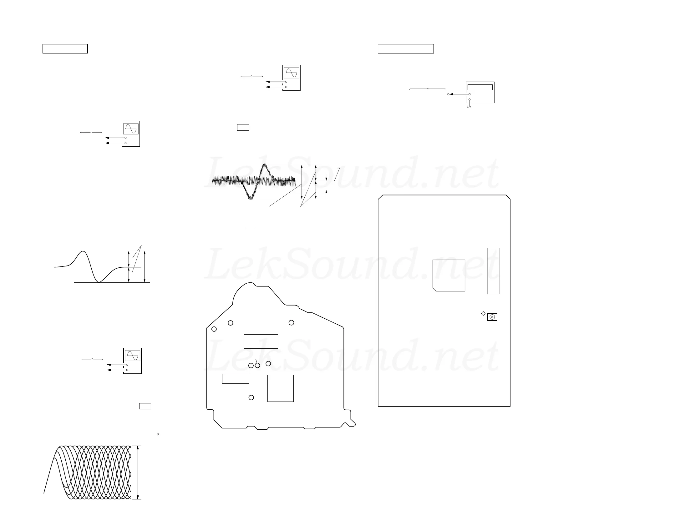
Frequency Adjustment
Connection:
Procedure:
1. Connect the frequency counter to TP508 (27 MHz) on VIDEO
board.
2. Turn the power ON.
3. Press the [FUNCTION] button to select the CD.
4. Adjust CT503 on the VIDEO board so that the frequency
counter reading 27.0 MHz ± 80 Hz at stop status.
Adjustment Location:
+
–
TP508 (27 MHz)
VIDEO board
frequency counter
IC505
IC507
TP508
(27 MHz)
CT503
VIDEO
Frequency
Adjustment
– VIDEO BOARD (Side A) –
Note:
1. CD Block is basically designed to operate without adjustment. There-
fore, check each item in order given.
2. Use YEDS-18 disc (3-702-101-01) unless otherwise indicated.
3. Use an oscilloscope with more than 10 MΩ impedance.
4. Clean the object lens by an applicator with neutral detergent when the
signal level is low than specified value with the following checks.
S-Curve Check
Procedure:
1. Connect oscilloscope to TP (FE) and TP (VC).
2. Connect between TP (FE1) and TP (VC) by lead wire.
3. Connect between TP (AGCCON) and TP (GND) by lead wire.
4. Turn the power ON.
5. Load a disc (YEDS-18) and actuate the focus search. (In con-
sequence of open and close the disc tray, actuate the focus
search)
6. Cofirm that the oscilloscope waveform (S-curve) is symmetri-
cal between A and B. And confirm peak to peak level within
4 ± 1 Vp-p.
S-curve waveform
7. After check, remove the lead wire connected in step 2 and 3.
Note: • Try to measure several times to make sure than the ratio of A : B
or B : A is more than 10 : 7.
• Take sweep time as long as possible and light up the brightness
to obtain best waveform.
RF Level Check
Procedure:
1. Connect oscilloscope to TP (RF) and TP (VC).
2. Connect between TP (AGCCON) and TP (GND) by lead wire.
3. Turn the power ON.
4. Load a disc (YEDS-18) and press the G X button to play.
5. Confirm that the oscilloscope waveform is clear and check RF
signal level is correct or not.
6. After check, remove the lead wire connected in step 2.
Note: Clear RF signal waveform means that the shape “ ” can be clearly
distinguished at the center of the waveform.
CD SECTION
+
–
BD board
TP (FE)
TP (VC)
oscilloscop
A
B
symmetry
within 4 ± 1 Vp-p
+
–
BD board
TP (RF)
TP (VC)
oscilloscop
(AC range)
VOLT/DIV: 200 mV
TIME/DIV: 500 ns
(with the 10: 1 probe
in use)
level:
1.45 ± 0.3 Vp-p
E-F Balance (1 Track Jump) Check
Procedure :
1. Connect oscilloscpe to TP (TE) and TP (VC).
2. Turn the power ON.
3. Load a disc (YEDS-18) and playback the number five track.
4. Press the G X button. (Becomes the 1 track jump mode)
5. Confirm that the level B and A (DC voltage) on the oscillo-
scope waveform.
1 track jump waveform
Specified level: × 100 = less than ± 22%
6. After check, remove the lead wire connected in step 1.
Checking Location:
A
B
+
–
BD board
TP (TE)
TP (VC)
oscilloscope
(DC range)
A (DC voltage
center of
waveform
B
0V
level = 1.3 ± 0.6 Vp-p symmetry
TP (AGCCON)
TP (RF)
TP (GND)
TP (FE)
IC103
IC102
IC101
TP (FE1)
TP (VC)
TP (TE)
– BD BOARD (Side B) –
LekSound.net
LekSound.net
LekSound.net
 Loading...