2-1
HDR-TG1/TG1E/TG3E_L2
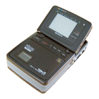
Cut and remove the part of gilt
which comes off at the point.
(Be careful or some
pieces of gilt may be left inside)
NOTE FOR REPAIR
• Make sure that the flat cable and flexible board are not cracked of bent at the terminal.
Do not insert the cable insufficiently nor crookedly.
• When remove a connector, don’t pull at wire of connector. It is possible that a wire is snapped.
• When installing a connector, don’t press down at wire of connector.
It is possible that a wire is snapped.
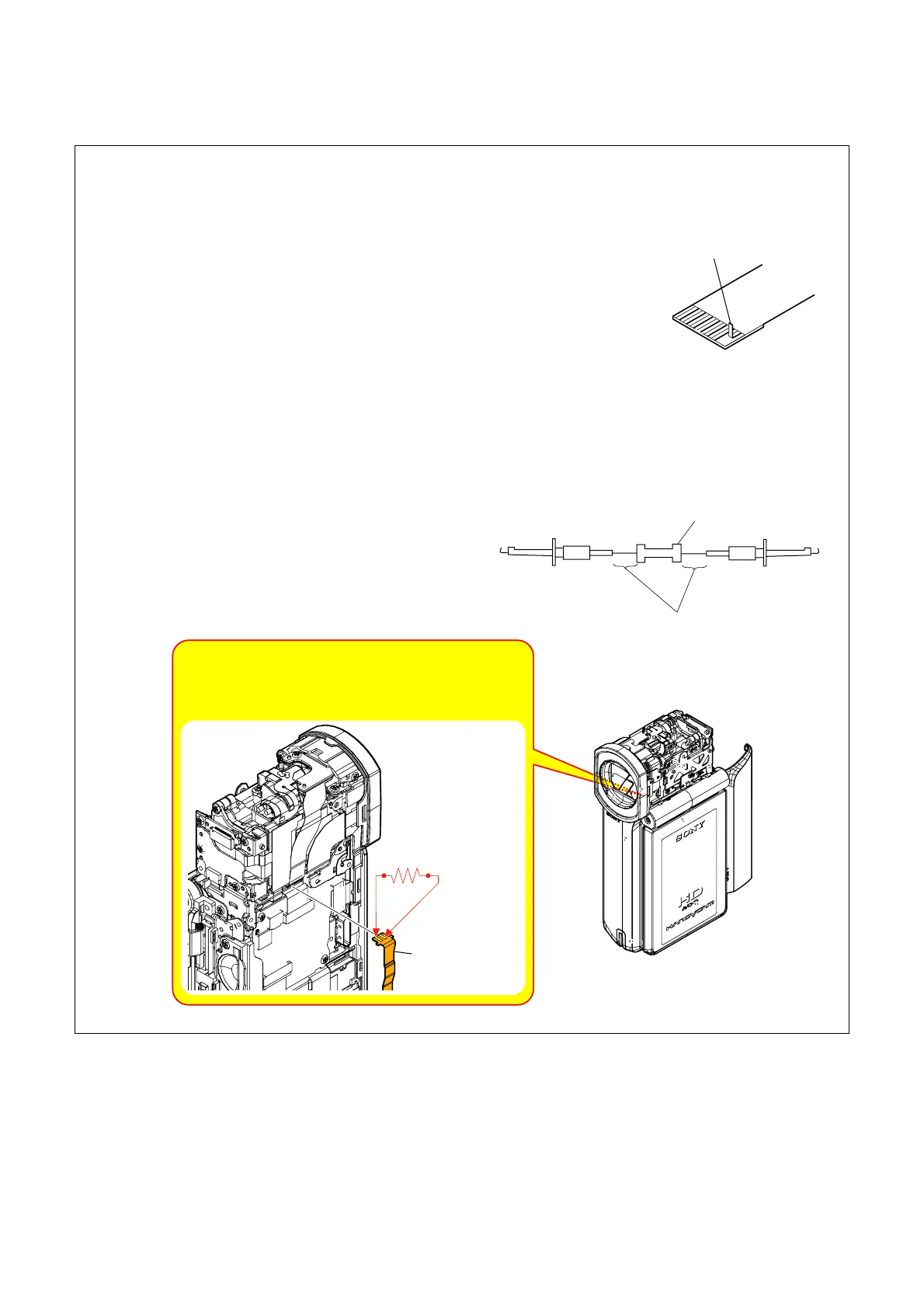
DISCHARGING OF FP-914 FLEXIBLE BOARD’S CHARGING CAPACITOR (C001)
The charging capacitor (C001) of FP-914 flexible board is
charged up to the maximum 330 V potential.
There is a danger of electric shock by this high voltage when the
capacitor is handled by hand. The electric shock is caused by
the charged voltage which is kept without discharging when the
main power of the unit is simply turned off. Therefore, the
remaining voltage must be discharged as described below.
1 kΩ/1 W
Wrap insulating tape.
Note: High-voltage cautions
Discharging the Capacitor
Short-circuit between two points
with the short jig about 10 seconds.
FP-914
Flexible Board
R:1 kΩ/1 W
(Part code: 1-215-869-11)
Preparing the Short Jig
To preparing the short jig, a small clip is attached to each end of
a resistor of 1 kΩ /1 W (1-215-869-11).
Wrap insulating tape fully around the leads of the resistor to
prevent electrical shock.
2. DISASSEMBLY

 Loading...