NEX-VG30/VG30E/VG30EH/VG30H_L2
2-5
2-1-3. OVERALL SECTION-2
DISASSEMBLY
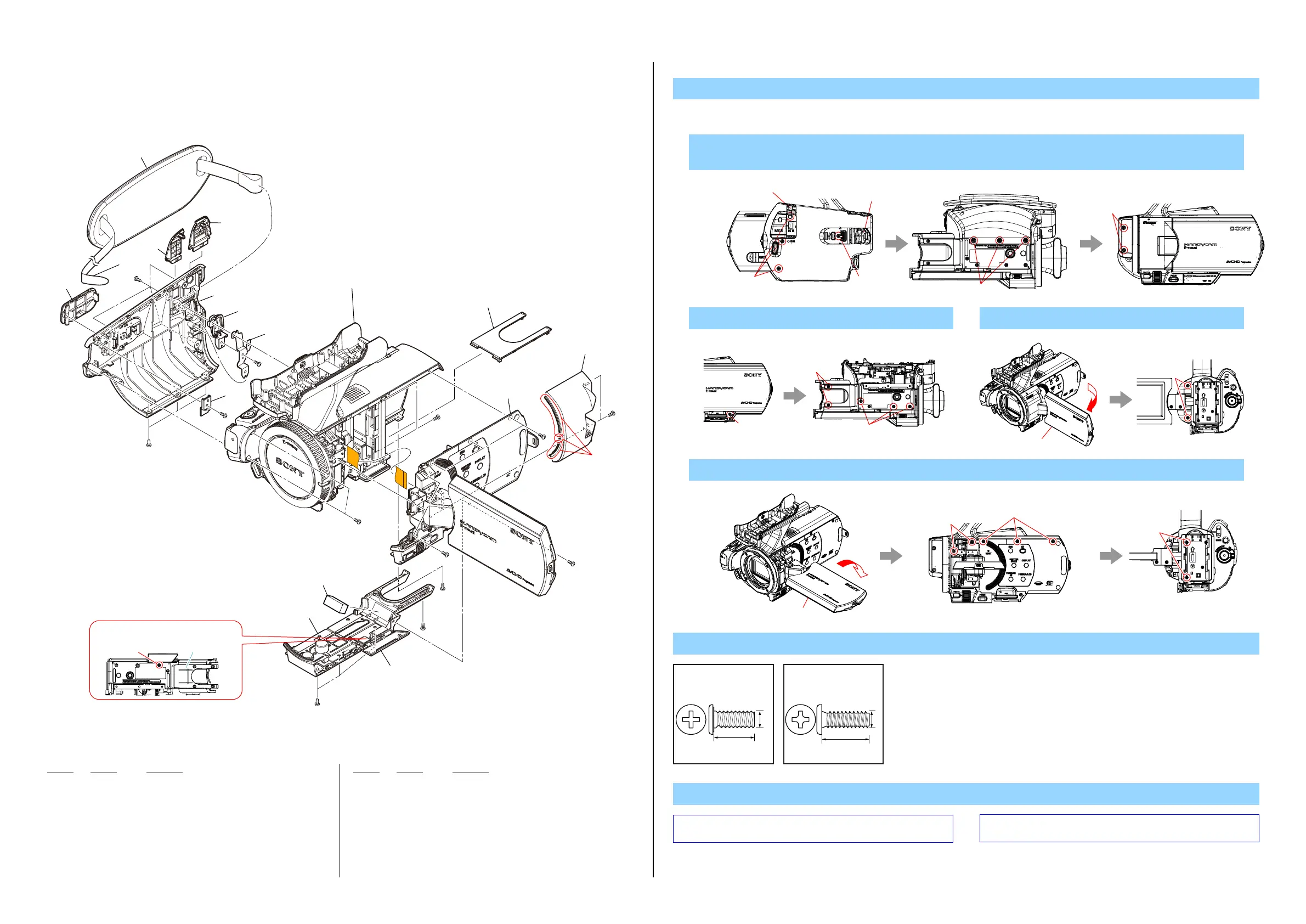
1. Remove in numerical order (1 to 4) in the left figure.
1 Remove the Grip Belt (1-1) → #2 X 2 → Open the DC Cover (1-2) → #2 X 1 →
Open the HM Cover (1-3) → #2 X 1 → #2 X 3 → #12 X 2
2 Open the HD Lid (2-1) → #2 X 6
3 Open the LCD (3-1) → #2 X 2
4 Remove the BT Lower Panel (4-1) → Rotate the LCD (4-2) → #2 X 7
Note
Screw
Ref. No. Part No. Description Ref. No. Part No. Description
101 X-2585-480-1 CABINET (BM (435)) ASSY
102 4-260-917-01 GASKET (BM)
103 4-299-882-01 RETAINER, HM COVER
104 4-299-885-01 BRACKET (REAR), BELT
105 4-299-883-01 GUARD, GRIP BELT
106 4-299-148-01 CABINET (G)
107 4-299-147-01 COVER, HM
108 4-299-153-01 COVER, DC
109 4-299-152-01 COVER, HP
110 4-299-884-01 BELT, GRIP
111 4-257-733-01 PANEL, BT LOWER
112 4-299-155-01 CABINET, HINGE
#2 2-635-562-31 SCREW (M1.7)
#12 3-080-204-21 SCREW, TAPPING, P2
Left View Bottom View Right View
#2
#2
#2
#12
1-2
1-3
3-1
Back View
#2
Right View Bottom View
#2
#2
#2
#2
Right View
Back View
#2
#2
4-2
Note: Refer to “Assembly-1: Installation Cautions of the Cabinet (R)
Section.”.
Note:
“Assembly-1: Installation Cautions of the Cabinet (R)
Section.” を参照してください。
#2: M1.7 X 4.0
(Black)
2-635-562-31
4.0
1.7
#12: M1.7 X 5.0 (Tapping)
(Black)
3-080-204-21
1.7
5.0
Screw
Cabinet (BM) Assy
Make sure not to remove the screw
indicated in figure.
4 Cabinet (R) Section
(See page 2-6)
(Note)
Handle Block Section
(See page 2-8)
1 106
2 101
3 112
102
3 (Claws
111
105
104
103
108
110
107
109
4-1
1-1
#2
#12
#12
#2
#12
#2
#2
#2
#2
#2
#2
#2
#2
2-1
 Loading...