 Loading...
Do you have a question about the Sony NEX-VG30 and is the answer not in the manual?
| Effective Pixels | 16.1 MP |
|---|---|
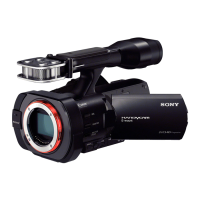
| Lens Mount | Sony E-mount |
| Display | 3.0" LCD |
| Microphone | Built-in Stereo Microphone |
| Headphone Jack | Yes |
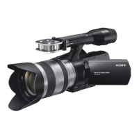
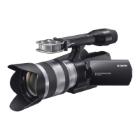
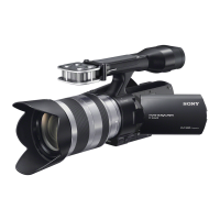
| Type | Camcorder |
| Sensor Type | CMOS |
| Sensor Size | 23.5 x 15.6 mm (APS-C) |
| Video Resolution | 1920 x 1080 |
| Frame Rate | 60p, 60i, 24p |
| Video Format | AVCHD, MP4 |
| Audio Format | Dolby Digital |
| Focus System | Contrast Detection AF |
| Storage Media | Memory Stick PRO Duo/SD/SDHC/SDXC |
| Microphone Input | Yes (3.5mm) |
| HDMI Output | Yes (mini HDMI) |
| USB Port | Yes |
| Battery | NP-FV70 |
| Image Stabilization | Optical SteadyShot (lens dependent) |
Procedure to prevent unit shutdown during repair by ensuring continuous power supply.
Notes on replacing VC-1011 board, including data handling and serial number input.
Instructions for replacing EVF display (LCD902) or VC board, including WB adjustment values.
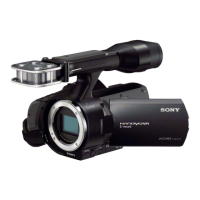
Detailed procedures for replacing MB N Plate washers, ensuring correct dimensions and assembly.
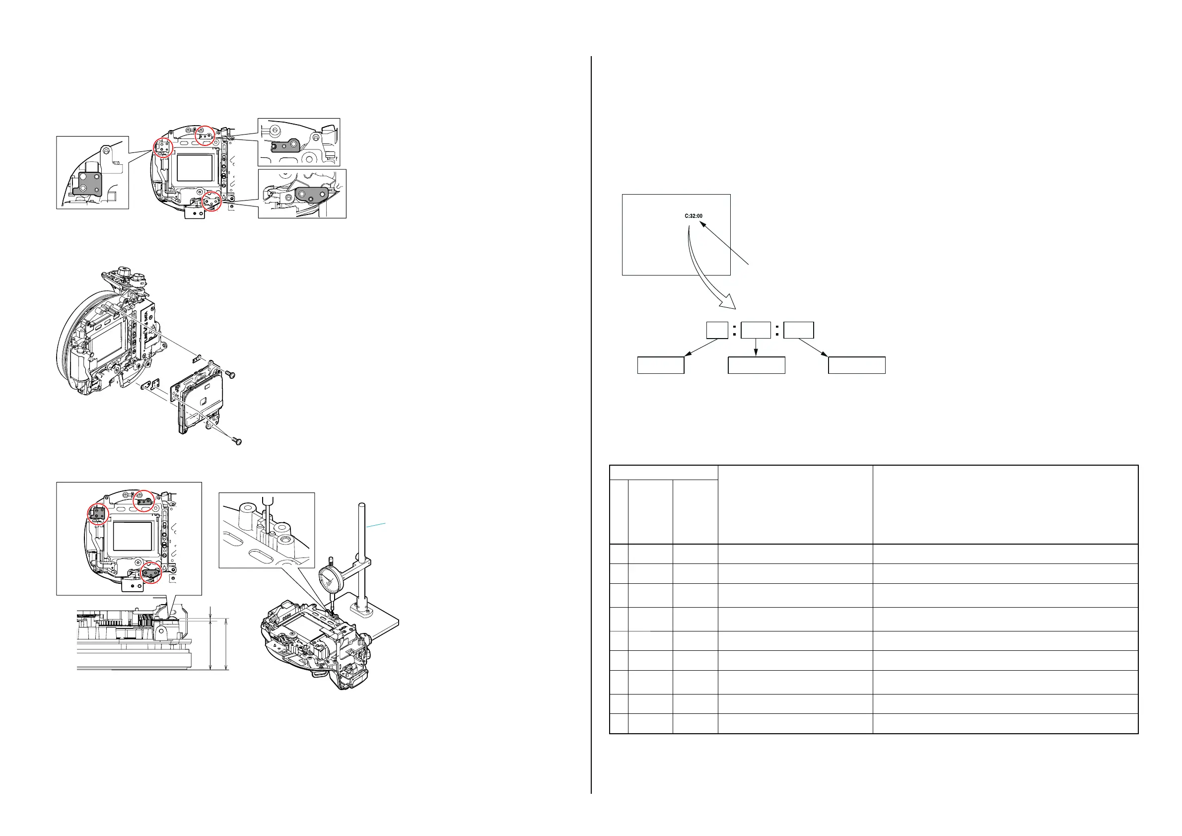
Explanation of the self-diagnosis function, error codes, and troubleshooting steps for unit malfunctions.
Steps to identify and resolve lens errors, including checking error codes and component replacements.
Highlights critical components for safety and the need for specified replacement parts.
Essential safety checks to perform after service work before returning the unit to the customer.
Guide to identifying parts using reference numbers and understanding component markings for safety.
Detailed exploded view and step-by-step disassembly instructions for the main chassis and accessories.
Step-by-step guide for cleaning the Optical Low Pass Filter (OLPF) using specific tools and solutions.