BDP-S7200
6-3
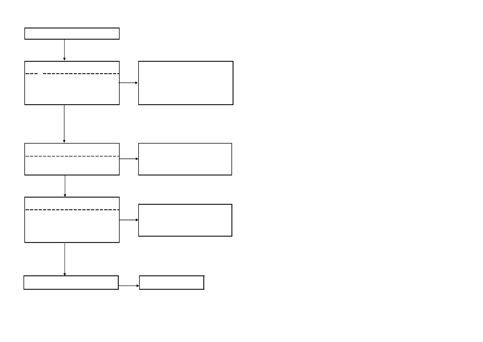
6-2. Power (System) Flow
AC IN
Check the output voltages from the power
supply block.
CN301 pin 1: +12V (UNSW12V)
CN301 pin 2: +12V (UNSW12V)
CN301 pin 3: +12V (FE_UNSW12V)
No
Yes
Check the fuses
Have any of the below fuses blown?
No
MB board: PS301, PS302
Yes
Check the following power control signals
while the power is ON
PCONT1# : MB board
Is PCONT1# : 3.3V ?
R327, R343,R388
Yes
Check Voltage lines that are not output
are shorted
to GND
No
Failure of power supply IC ->
Replace the MB board .
Check that the harness has been inserted
properly. If there is no problem, replace the
power supply block.
Blown fuses ->
Replace the MB board
No
Failure of Reset IC. Replace MB Board.
 Loading...