HT-CT290/CT291
10
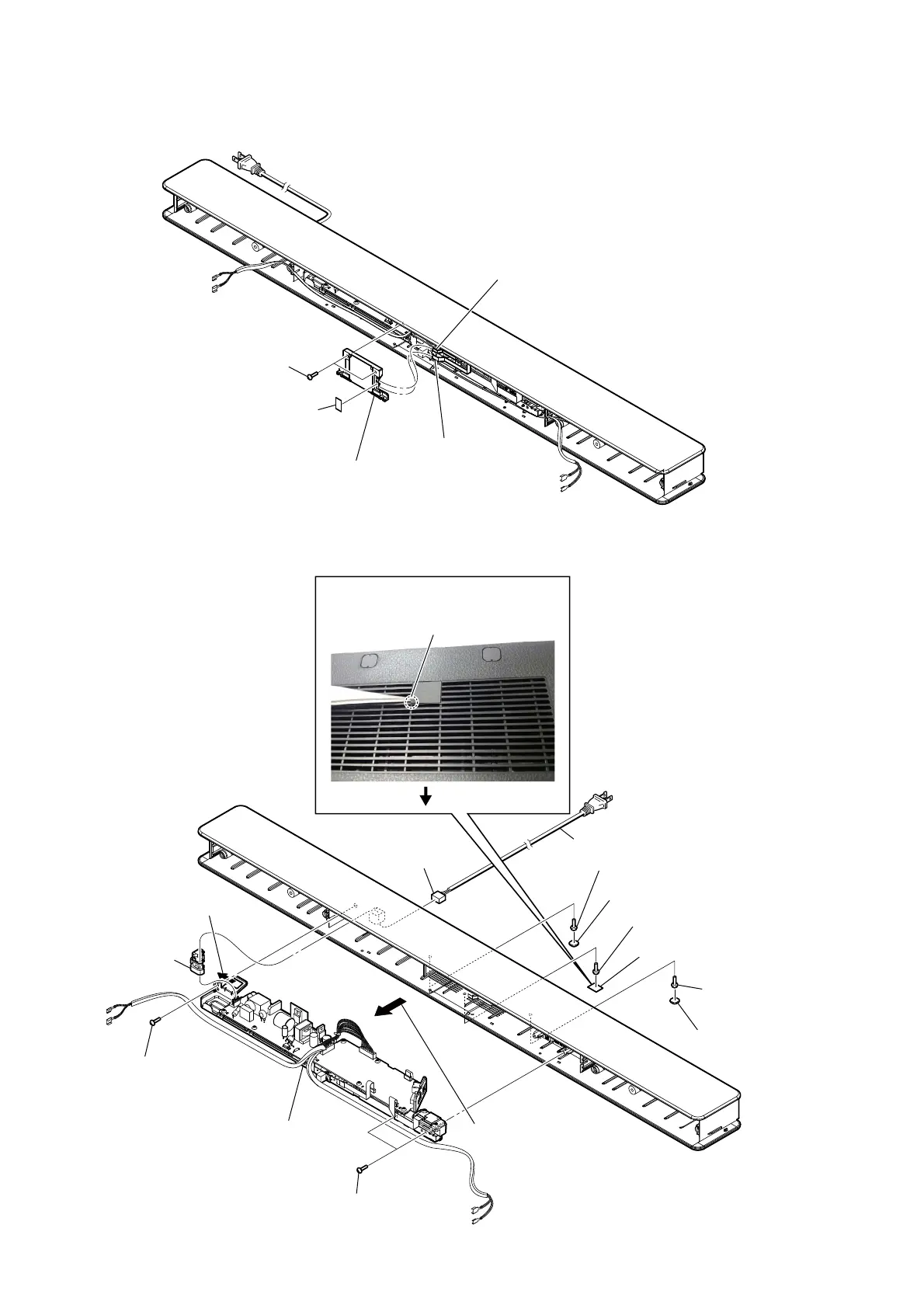
2-3. DISP CHUKEI BOARD SECTION
2-4. CHASSIS SECTION
6 one screw
(TPP + 3 u 10 (HR) - 3W ZN)
6 two screws
(TPP + 3 u 10
(HR) - 3W ZN)
qs chassis section
7 Remove the chassis section
in the direction of an arrow.
8 Remove the
cord, power.
9 bushing (FBS001),
cord
2 one screw
(TPP + 3 u 10
(HR) - 3W ZN)
5 one screw
(TPP + 3 u 10 (HR) - 3W ZN)
2 one screw
(TPP + 3 u 10 (HR) - 3W ZN)
0 CN1
1 foot (CG-BAR)
4 cover (CG-BAR)
1 foot (CG-BAR)
qa cord, power
3 Insert the tweezer into the service hole
and raise the cover (CG BAR).
service hole
rear side
4 two screws
CASE 3 TP2
1 cushion, window
5 DISP CHUKEI board section
2 wire (flat type) (6 core)
(CN5003)
3 wire (flat type)
(16 core) (CN5001)
 Loading...