7
STR-DG910
13
US
Getting Started
Name Function
O DVD TOP
MENU
Press to display the menu or
on-screen guide of the DVD
player on the TV screen.
Then, use V/v/B/b and to
perform menu operations.
DVD MENU Press to display the menu of
the DVD player on the TV
screen. Then, use V/v/B/b
and to perform menu
operations.
P MUTING Press to mute the sound (page
42).
To mute the sound of the TV,
press TV (wj) and then press
MUTING.
Q TV VOL +/– Press TV (wj) and then press
TV VOL +/– to adjust the TV
volume level.
MASTER
VOL +/–
Press to adjust the volume
level of all speakers at the
same time.
R DISC SKIP Press to skip disc of the CD
player, VCD player, DVD
player, or MD deck (multi-
disc changer only).
S REPLAY /
ADVANCE
Press to replay the previous
scene or fast forward the
current scene of the DVD
player, Blu-ray disc recorder,
DVD/VHS COMBO, or
DVD/HDD COMBO.
CATEGORY
+/–
Press to select a category for
XM Radio (page 74).
T RETURN/
EXIT O
Press to
–return to the previous menu.
–exit the menu while the
menu or on-screen guide of
the VCD player, LD player,
DVD player, Blu-ray disc
recorder, PSX, DVD/VHS
COMBO, or satellite tuner
is displayed on the TV
screen.
To return to the previous
menu of Sony TV, press TV
(wj) and then press
RETURN/EXIT O.
<
<
Name Function
U
V/v/B/b
After pressing RECEIVER
(D), press MENU (K) for
receiver operation, then press
V/v/B /b to select the
settings.
After pressing DVD TOP
MENU (O) or DVD MENU
(O), press V/v/B/b to select
the settings, and then press
to enter the selection.
Press also to enter the
selection of the receiver,
VCR, satellite tuner, DVD
player, Blu-ray disc recorder,
PSX, DVD/VHS COMBO, or
DVD/HDD COMBO.
V GUIDE Press to display the EPG
(Electronic Program Guide)
of the TV, DVD player,
satellite tuner, Blu-ray disc
recorder, PSX, or DVD/HDD
COMBO.
W CLEAR Press to clear a mistake when
you press the incorrect
numeric button of the DVD
player, Blu-ray disc recorder,
PSX, satellite tuner, DVD/
VHS COMBO, or DVD/HDD
COMBO.
-/-- Press to select the channel
entry mode, either one or two
digit of the VCR or satellite
tuner.
To select the channel entry
mode of the TV, press TV
(wj) and then press -/--.
>10 Press to select track numbers
over 10 of the CD player,
VCD player, LD player, MD
deck, tape deck, TV, VCR, or
satellite tuner.
X SLEEP Press to activate the Sleep
Timer function and the
duration which the receiver
turns off automatically.
Y CATEGORY
MODE
Press to select the category
mode for XM radio (page 73).
Z 2CH Press to select a sound field
(page 60, 62, 65)
A.F.D.
MOVIE
MUSIC
,
continued
14
US
a)
The number 5, TV CH +, PRESET + and H
buttons have tactile dots. Use the tactile dots as
references when operating the receiver.
b)
This button is also available for DIGITAL
MEDIA PORT adapter operation. For details on
the function of the button, see the operating
instructions supplied with the DIGITAL MEDIA
PORT adapter.
Notes
•Some functions explained in this section may not
work depending on the model.
•The above explanation is intended to serve as an
example only. Therefore, depending on the
component, the above operation may not be
possible or may operate differently than described.
Name Function
wj TV Press to light up the button. It
changes the remote key
function to activate the
buttons with orange printing.
It also activate the DISPLAY
(I), OPTIONS TOOLS
(J), MENU (K),
RETURN/EXIT O (T),
(U), and V/v/B/b (U)
buttons to perform menu
operations for Sony TVs only.
wk RM SET UP Press to set up the remote.
AEP, UK, E2 model:
4
GB
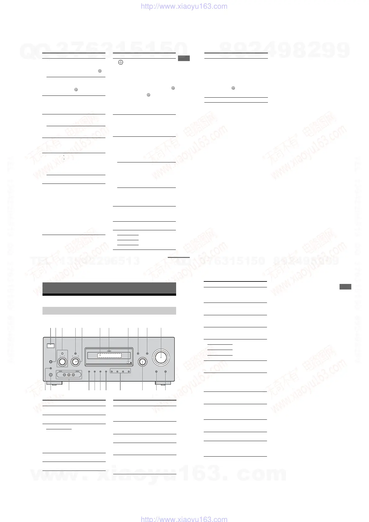
Description and location of parts
.
Getting Started
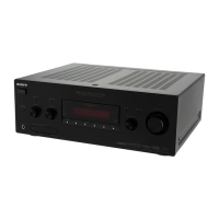
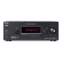
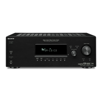
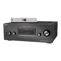
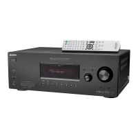
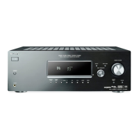
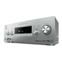
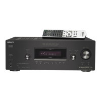
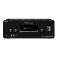
Front panel
?/1
AUTO CAL MIC
SPEAKERS
(OFF/A/B/A+B)
PHONES
VIDEO 3 IN/PORTABLE AV IN
VIDEO L AUDIO R
MEMORY/
ENTER DIMMER 2CH
SUR BACK
DECODING
SLEEP A.F.D. MOVIE MUSIC
AUTO CAL DIRECT
INPUT SELECTOR
TONE MODE
TUNINGTONE
6 74
8
qs
qd
1 32 59q; qa
qfqgwa qhw;ws
qk qjql
DISPLAY INPUT MODE
MASTER VOLUME
MULTI CHANNEL DECODING
TUNING MODE
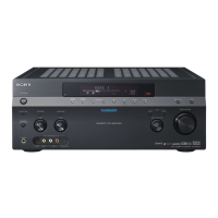
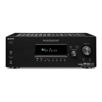
Name Function
A ?/1
(on/standby)
Press to turn the receiver on
or off (page 32, 42, 43, 65).
B SPEAKERS
(OFF/A/B/A+B)
Press to select the speaker
system (page 33).
C TONE MODE Adjusts the tonal quality
(bass/treble level) of the
front speakers.
Press TONE MODE
repeatedly to select bass or
treble level, then turn
TONE +/– to adjust the
level (page 45).
TONE +/–
D TUNING MODE Press to select the tuning
mode (page 66, 68).
E TUNING +/– Turn to scan a station (page
66, 68).
Name Function
F Display The current status of the
selected component or a list
of selectable items appears
here (page 6).
G MULTI
CHANNEL
DECODING lamp
Lights up when multi
channel audio signals are
decoded (page 43).
H Remote sensor Receives signals from
remote commander.
I DISPLAY Press to select information
displayed on the display
(page 70, 76).
J INPUT MODE Press to select the input
mode when the same
components are connected
to both digital and analog
jacks (page 71).
5
GB
Getting Started
Name Function
K MASTER
VOLUME
Turn to adjust the volume
level of all speakers at the
same time (page 39, 41, 42,
43).
L DIRECT Press to listen to high
quality analog sound (page
64).
M AUTO CAL Press to activate the Auto
Calibration function (page
35).
N INPUT
SELECTOR
Turn to select the input
source to playback (page
40).
O 2CH Press to select a sound field
(page 59, 61, 64).
A.F.D.
MOVIE
MUSIC
P SUR BACK
DECODING
Press to select the surround
back decoding mode (page
51).
Q SLEEP Press to activate the Sleep
Timer function and the
duration which the receiver
turns off automatically
(page 77).
R DIMMER Press to adjust the
brightness of the display
(page 58).
S MEMORY/
ENTER
Press to store a station or
enter the selection when
selecting the settings (page
32, 67).
T VIDEO 3 IN/
PORTABLE AV
IN jacks
Connects to a camcorder or
video game (page 27, 41).
U PHONES jack Connects to headphones
(page 87).
V AUTO CAL MIC
jack
Connects to the supplied
optimizer microphone for
the Auto Calibration
function (page 34).
w
w
w
.
x
i
a
o
y
u
1
6
3
.
c
o
m
Q
Q
3
7
6
3
1
5
1
5
0
9
9
2
8
9
4
2
9
8
T
E
L
1
3
9
4
2
2
9
6
5
1
3
9
9
2
8
9
4
2
9
8
0
5
1
5
1
3
6
7
3
Q
Q
TEL 13942296513 QQ 376315150 892498299
TEL 13942296513 QQ 376315150 892498299
http://www.xiaoyu163.com
http://www.xiaoyu163.com
 Loading...