53
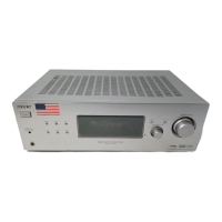
STR-K7000
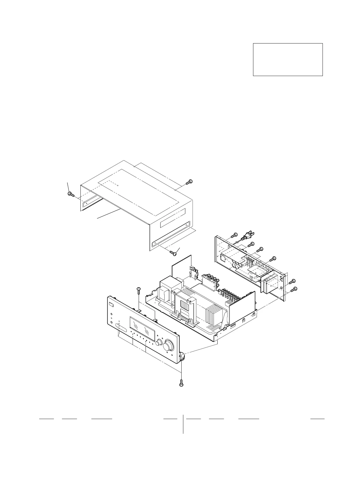
SECTION 5
EXPLODED VIEWS
Ref. No. Part No. Description Remark
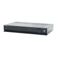
5-1. CASE SECTION
Ref. No. Part No. Description Remark
12-661-145-11 CASE
23-363-099-02 SCREW (CASE 3 TP2)
#1 7-685-646-79 SCREW +BVTP 3X8 TYPE2 IT-3
NOTE:
• The mechanical parts with no reference
number in the exploded views are not supplied.
• Items marked “*” are not stocked since
they are seldom required for routine service.
Some delay should be anticipated
when ordering these items.
• -XX and -X mean standardized parts, so
they may have some difference from the
original one.
• Color Indication of Appearance Parts
Example :
KNOB, BALANCE (WHITE) ... (RED)
Parts Color Cabinet’s Color
• Accessories are given in the last of this parts list.
R
R
The components identified by
mark 0 or dotted line with mark
0 are critical for safety.
Replace only with part number
specified.
1
2
2
#1
#1
#1
#1
#1
#1
#1
#1
#1
 Loading...