3
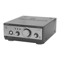
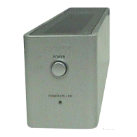
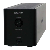
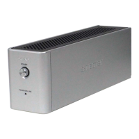
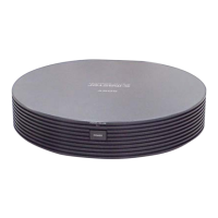
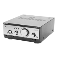
TA-S7AV
SECTION 1
SERVICING NOTES
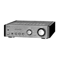
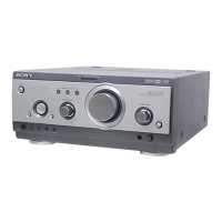
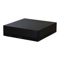
This set is a component of the MHC-S7AV.
The MHC-S7AV system configuration is as shown below, and
therefore it does not operate normally unless all four components
are connected.
In performing the repair, connect all components with the system
cables.
Note: The precaution to the users is described on the label stuck
on the back panel (CD player) and in the troubleshooting section
in the Operation Manual.
System Configuration:
POWER SUPPLY
AC IN
TA
SYSTEM & CD
µ
con
ST
CDP
TC
µ
con
TC
DISPLAY
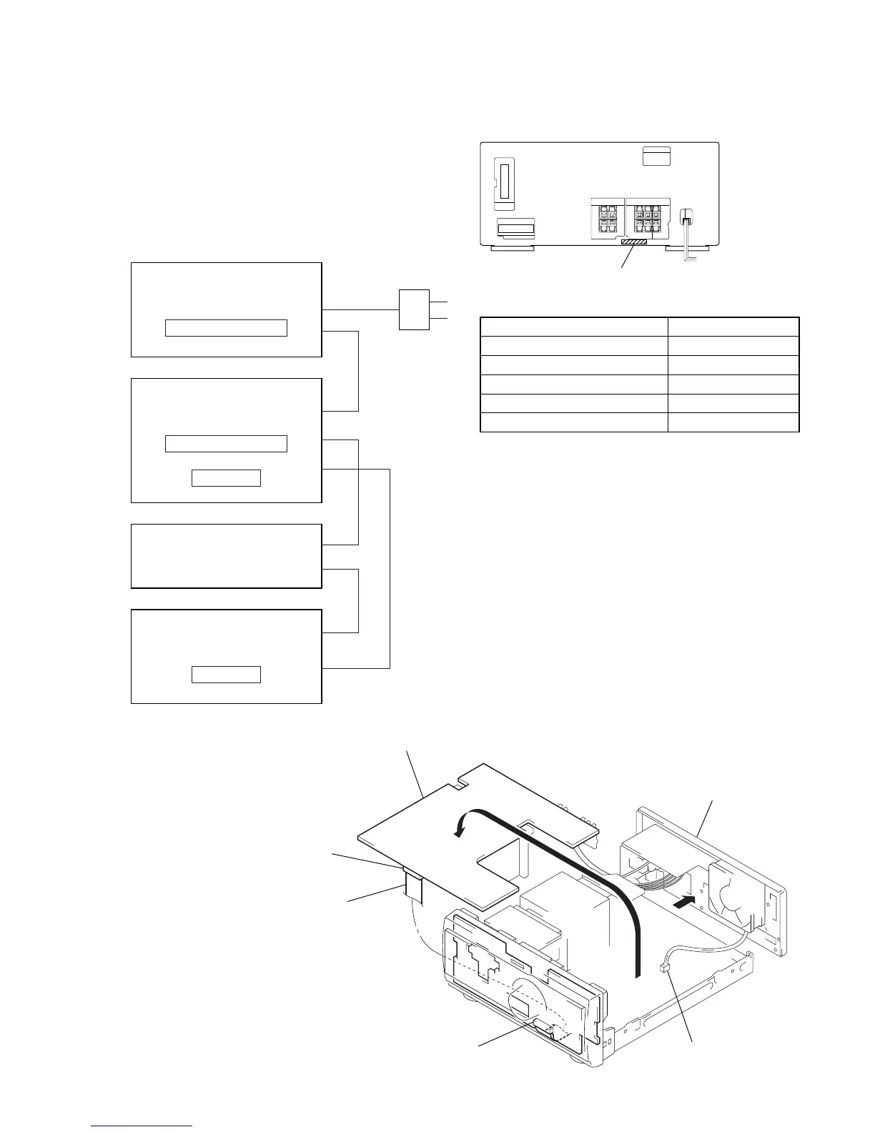
MODEL IDENTIFICATION
– Back Panel –
PART No.
Model PART No.
AEP model 4-232-337-0
[]
UK model 4-232-337-3
[]
Australian model 4-232-337-5
[]
Mexican model 4-232-337-7
[]
Korean model 4-232-337-8
[]
FRONT AMP BOARD SERVICE POSITION
In checking the FRONT AMP board, prepare jig
(extension cable J-2501-019-A: 1.25 mm Pitch, 25 core, Length
300 mm) (Australian, Mexican and Korean models)
(extension cable J-2501-087-A: 1.25 mm Pitch, 23 core, Length
300 mm) (AEP, UK models)
(Fig A)
Turn over the FRONT AMP board with Heat Sink,
SURROUND AMP board and RELAY board connected.
Remove the back panel
(AV) section.
Remove the fan motor
connector lead wire.
FRONT AMP board
(CN104)
Connect jig (extension
cable J-2501-019-A (Australian,
Mexican and Korean models),
J-2501-087-A (AEP, UK models)
to the FRONT AMP board (CN104)
and PANEL board (CN700).
PANEL board (CN700)
(Fig A)
 Loading...