— 2 —
Section Title Page
SECTION 1. GENERAL ...............................................3
SECTION 2. SERVICE NOTE .....................................4
SECTION 3. DISASSEMBLY
3-1. Cassette Lid ASSY and Case ASSY ................................. 6
3-2. Bracket ASSY and Cassette Holder ASSY ....................... 6
3-3. Tuner Board ....................................................................... 7
3-4. Main Board......................................................................... 7
SECTION 4. MECHANICAL ADJUSTMENT ...........8
SECTION 5. ELECTRICAL ADJUSTMENT .............8
SECTION 6. DIAGRAMS
6-1. Printed Wiring Board — Tuner Section —..................... 11
6-2. Schematic Diagram — Tuner Section — ........................ 13
6-3. Schematic Diagram — Main Section — ......................... 17
6-4. Printed Wiring Board — Main Section —...................... 21
6-5. IC Pin Functions
IC501 BA3641FV REC AMP ......................................... 25
IC701 MSM63120B System Control .............................. 25
IC702 SMC62L3A LCD Drive ....................................... 27
SECTION 7. EXPLODED VIEWS
7-1. Case Section ..................................................................... 28
7-2. Main Board Section ......................................................... 29
7-3. Mechanism Section (MF-WMGX614-112)..................... 30
SECTION 8. ELECTRICAL PARTS LIST ..............31
TABLE OF CONTENTS
SAFETY-RELATED COMPONENT WARNING !!
COMPONENTS IDENTIFIED BY MARK ! OR DOTTED
LINE WITH MARK ! ON THE SCHEMATIC DIAGRAMS
AND IN THE PARTS LIST ARE CRITICAL TO SAFE
OPERATION. REPLACE THESE COMPONENTS WITH
SONY PARTS WHOSE PART NUMBERS APPEAR AS
SHOWN IN THIS MANUAL OR IN SUPPLEMENTS
PUBLISHED BY SONY.
Notes on chip component replacement
• Never reuse a disconnected chip component.
• Notice that the minus side of a tantalum capacitor may be
damaged by heat.
Flexible Circuit Board Repairing
• Keep the temperature of the soldering iron around 270 °C
during repairing.
• Do not touch the soldering iron on the same conductor of
the circuit board (within 3 times).
• Be careful not to apply force on the conductor when solder-
ing or unsoldering.
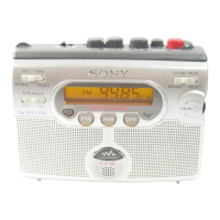
Dry Battery
 Loading...