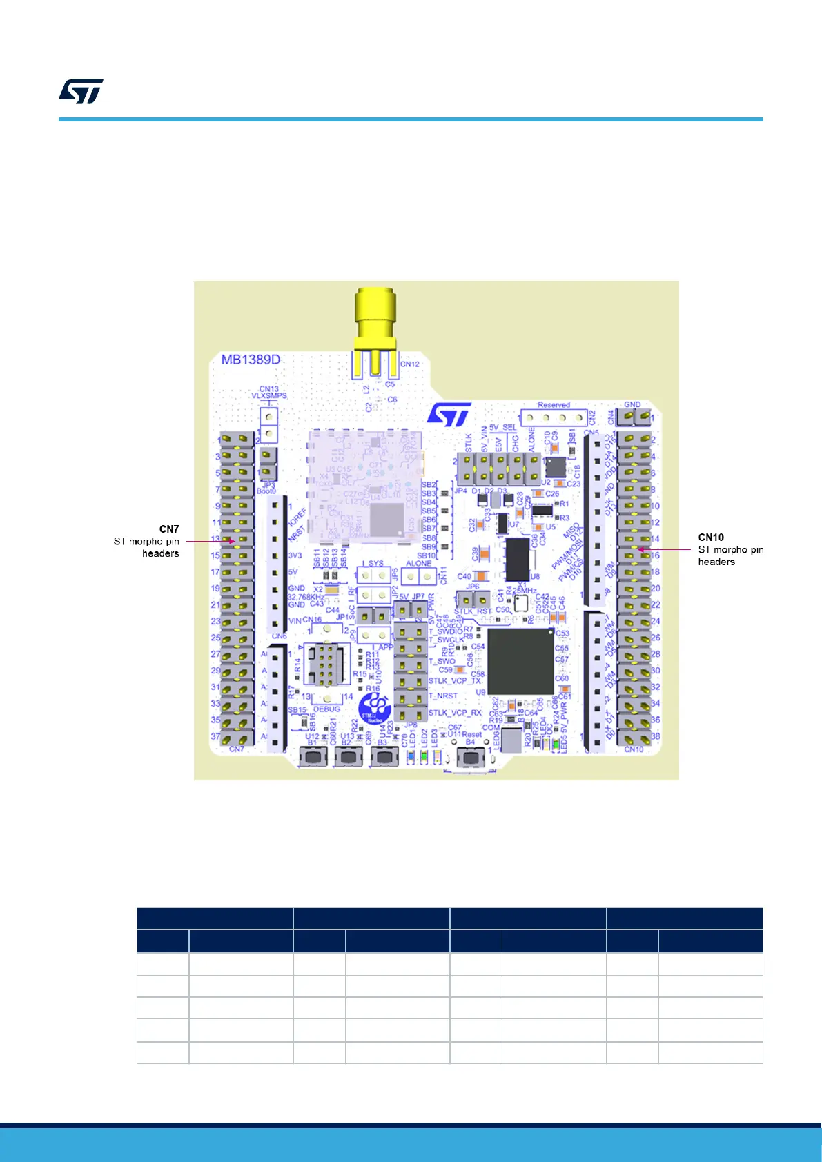
7.5 CN7 and CN10 ST morpho connectors
CN7 and CN10 ST morpho connectors are male pin headers accessible on both sides of the board. All signals
and power pins of the STM32WL MCU are available on the morpho connectors. These connectors can also be
probed by an oscilloscope, logical analyzer, or voltmeter.
Figure 24. ST morpho connectors
Note: The D0 and D1 signals are connected by default to USART1 (MCU I/O PB6 and PB7). Refer to
Section 6.6.5 for details about how to modify the UART interface.
Table 18 shows the pin assignment of each STM32WL I/O on the ST morpho connector.
Table 18. Pin assignment of the ST morpho connectors
CN7 odd pins
CN7 even pins CN10 odd pins CN10 even pins
Pin nbr Pin name Pin nbr
Pin name
(1)
Pin nbr
Pin name
(1)
Pin nbr Pin name
1 NC 2 NC 1 PA0 2 PC4
3 NC 4 NC 3 PA12 4 PC5
5 VDD_MCU 6 E5V 5 PA11 6 NC
7 BOOT0 8 GND 7 AVDD 8
5V_USB_CHGR
(2)
9 NC 10 NC 9 GND 10 NC
UM2592
CN7 and CN10 ST morpho connectors
UM2592 - Rev 1
page 36/49
 Loading...


