List of figures
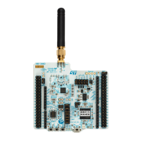
Figure 1. NUCLEO-WL55JC top view ...........................................................1
Figure 2. NUCLEO-WL55JC bottom view ........................................................1
Figure 3. Hardware block diagram .............................................................8
Figure 4. Top layout .......................................................................9
Figure 5. RF certification and UID64 stickers ..................................................... 10
Figure 6. Bottom layout .................................................................... 11
Figure 7. STM32WL Nucleo 73 board mechanical drawing (in millimeter) ................................. 12
Figure 8. USB composite device.............................................................. 13
Figure 9. Connecting an external debug tool to program the on-board STM32WL ............................ 14
Figure 10. STM32WL Nucleo-64 board power tree .................................................. 16
Figure 11. Power supply input from STLINK-V3E USB connector with PC (5 V, 500 mA maximum)................. 17
Figure 12. Power supply input from VIN (from 7 V to 12 V, 800 mA maximum) ............................... 19
Figure 13. Power supply input from 5V_EXT (5 V, 500 mA maximum) ..................................... 20
Figure 14. Power supply input from ST-LINK USB connector with 5 V USB charger ........................... 21
Figure 15. Power supply input from external 3V3 ................................................... 22
Figure 16. Power supply input from STD_ALONE_5V (5V, 500mA maximum) ............................... 23
Figure 17. STD_ALONE_5V and GND pins on CN11 ................................................ 23
Figure 18. RF block diagram ................................................................. 27
Figure 19. JP1 and JP4 settings for current consumption measurement ................................... 28
Figure 20. USB Micro-B connector CN23 (front view) ................................................ 32
Figure 21. MIPI10 debugging connector CN16 (top view) ............................................. 32
Figure 22. CN12 SMA connector .............................................................. 33
Figure 23. ARDUINO
®
connectors ............................................................. 34
Figure 24. ST morpho connectors ............................................................. 36
UM2592
List of figures
UM2592 - Rev 1
page 48/49

 Loading...