Option Byte programming in RDP level 0.5
Issue: The user cannot program non-secure option bytes in RDP level 0.5 through the bootloader.
Workaround: The user can program option bytes, thanks to STM32CubeProgrammer GUI or command-line
interfaces through JTAG. To know how to program option bytes through STM32CubeProgrammer, refer to
STM32CubeProgrammer user manual (UM2237).
Impossible to set TZEN option bit
Issue: The user cannot set the TZEN option bit through Bootloader interfaces.
Workaround: Instead of the bootloader interface, the user can use JTAG to set the TZEN option bit.
Go command on USB-DFU interface
Issue: The user cannot use Go command through the bootloader on the USB-DFU interface.
Workaround: Instead of the USB-DFU interface, the user can use JTAG or any other communication ports
supported by Bootloader to run Go command, like USART, I
2
C, SPI or CAN FD.
6.11.2 Boot from RSS
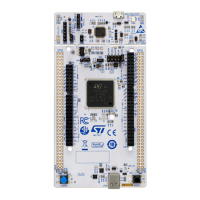
On the NUCLEO-L552ZE-Q, PH3-BOOT0 is fixed to a LOW level allowing the boot from the memory address
defined by SECBOOTADD0 option byte. In order to change the boot from RSS, it is necessary to set PH3-BOOT0
to the HIGH level just by applying 3V3 on the PH3-BOOT0 signal. The easiest solution is to make a direct
connection between CN11 pin 5 (VDD) and 7 (PH3_BOOT0).
6.12 Virtual COM port: LPUART or USART
An LPUART or a USART interface of STM32 microcontroller on NUCLEO board can be connected to ST-LINK/
V2-1 MCU or on shields on ST morpho connectors and ARDUINO
®
Uno V3 connectors.
The selection between LPUART and USART is performed by setting related solder bridges.
Refer to Table 10 and Table 11 below for the UART or LPUART connection to VCP interfaces or ARDUINO
®
UART.
Table 10. LPUART1 connection
Solder bridge configuration
(1)
Feature
SB127, SB129 ON
SB124, SB126, SB128, SB130 OFF
LPUART1 (PG7/PG8) connected to ST-LINK VCP.
Must be the interface for 1V8 MCU mode because PG [2-15] stay at
3V3 IO interface link to the VDDIO power supply.
SB128, SB130 ON
SB123, SB125, SB127, SB129 OFF
LPUART1 (PG7/PG8) connected to Zio, ARDUINO
®
D0/D1
1. The default configuration is in bold.
Table 11. USART3 connection
Solder bridge configuration
(1)
Feature
SB124, SB126 ON
SB123, SB125, SB127, SB129 OFF
USART3 (PD8/PD9) connected to ST-LINK VCP
Only 3V3 mode supported
SB123, SB125 ON
SB124, SB126, SB128, SB130 OFF
USART3 (PD8/PD9) connected to Zio, ARDUINO
®
D0/D1
UM2581
Virtual COM port: LPUART or USART
UM2581 - Rev 2
page 26/48

 Loading...


