EasyManua.ls Logo

ST STM32L5 Nucleo-144 board User Manual

ST STM32L5 Nucleo-144 board
48 pages
To Next Page IconTo Next Page
To Previous Page IconTo Previous Page
Page #14 background imageLoading...
Page #14 background image
6.3.3.2 Using the ST-LINK/V2-1 to program and debug an external STM32 application
It is easy to use the ST-LINK/V2-1 to program the STM32 on an external application.
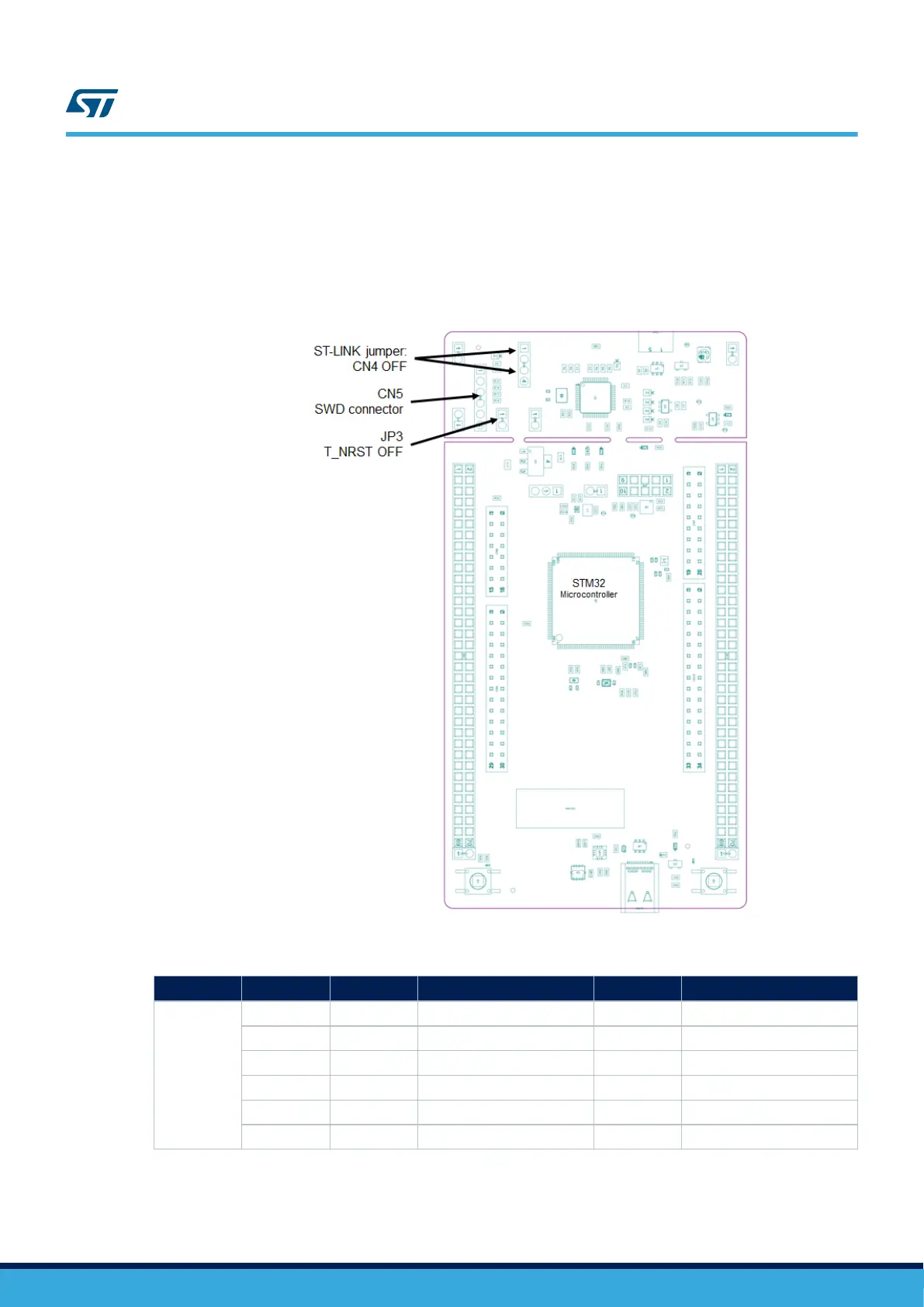
Simply remove the two jumpers from CN4, as shown in Figure 9, and connect your application to the SWD debug
connector (CN5) according to Table 6.
Note: JP3 T_NRST (target STM32 reset) must be open when CN5 pin 5 is used with an external application.
Figure 9. ST-LINK debugger: JP configuration for external MCU
Table 6. Debug connector SWD: pinning
Connector
Pin number Pin name Signal name STM32 pin Function
SWD CN5
1 1 VDD_TARGET: AIN_1 - VDD from application
2 2 T_JTCK - SWD clock
3 3 GND - Ground
4 4 T_JTMS - SWD data I/O
5 5 T_NRST - Reset of target MCU
6 6 T_SWO - SWD out (optional)
UM2581
Embedded ST-LINK/V2-1
UM2581 - Rev 2
page 14/48

Table of Contents

Question and Answer IconNeed help?

Do you have a question about the ST STM32L5 Nucleo-144 board and is the answer not in the manual?

ST STM32L5 Nucleo-144 board Specifications

General IconGeneral
BrandST
ModelSTM32L5 Nucleo-144 board
CategoryMotherboard
LanguageEnglish

Summary

Introduction

Features

Ordering information

Product marking

Explains markings on evaluation tools and the STM32 device, including 'ES' or 'E'.

Products and codification

Explains the meaning of the product codification based on MCU series, memory, and package.

Development environment

System requirements

Specifies the operating systems and hardware required for development toolchains.

Development toolchains

Lists supported software development tools like IAR, Keil, and STM32CubeIDE.

Demonstration software

Describes the preloaded demonstration software and its availability for download.

Conventions

Quick start

Getting started

Step-by-step guide to configure the board and launch the demonstration application.

Default board configuration

Details the default jumper settings and voltage configurations for the Nucleo board.

Hardware layout and configuration

STM32L5 Nucleo-144 board layout

Top layout of the STM32L5 Nucleo-144 board, identifying key connectors and components.

Mechanical drawing

Provides mechanical dimensions of the STM32L5 Nucleo-144 board in millimeters.

Embedded ST-LINK/V2-1

Drivers

Information about the required USB drivers for ST-LINK/V2-1 and installation.

ST-LINK/V2-1 firmware upgrade

Guidance on how to update the firmware for the onboard ST-LINK/V2-1 debugger.

NUCLEO ST-LINK/V2-1 hardware configuration

Configuration of ST-LINK/V2-1 using jumpers for on-board or external debugging.

Power supply

External power supply input

Details the various DC power sources that can be used to power the Nucleo board.

Programing/debugging when the power supply is not from ST-LINK (5V_STLK)

Procedure for external powering for programming/debugging without ST-LINK.

External power supply output

Describes the availability of 5V and 3V3 outputs for powering external devices.

Internal power supply

Details the board's internal power supply configurations, including 3V3 and 1V8.

LEDs

Push-buttons

IDD measurement

JP4 VDD_MCU voltage selection 1V8 or 3V3

OSC clock sources

LSE: OSC 32 KHz clock supply

Configuration options for the Low-Speed External (LSE) 32.768 kHz clock.

OSC clock supply

Configuration options for the High-Speed External (HSE) clock.

Reset sources

RSS/bootloader

RSS limitation

Specific limitations related to the RSS and bootloader functionality on the STM32L5.

Boot from RSS

Virtual COM port: LPUART or USART

USB Type-C™ FS

USB FS device

Describes how the Nucleo-144 board functions as a USB device via the Type-C™ connector.

UCPD

Explains the USB Power Delivery (UCPD) feature, including dead battery and SINK mode.

USB Type-C™ connector

Jumper configuration

Solder bridge configuration

Extension connectors

Zio connectors supporting ARDUINO® Uno V3

Information on ARDUINO® Uno V3 compatible Zio connectors (CN7-CN10) and their pinouts.

ST morpho connector CN11 and CN12

Limitation

RSS/bootloader limitation

Specific limitations related to the RSS and bootloader functionality on the STM32L5.

SMPS limitation

Limitations concerning the internal SMPS functionality on the STM32L5.

Federal Communications Commission (FCC) and Industry Canada (IC) Compliance Statements

FCC Compliance Statement

FCC compliance information including Part 15 rules and user guidance.

IC Compliance Statement

Industry Canada compliance statement and relevant label information.

CE conformity

Warning

CE conformity warning regarding Class B compliance and potential radio interference.

Revision history

Related product manuals