• V
BUS
fault detection: UCPD_FLT: This signal is provided by the STM USB Type-C
™
port protection. It is
used as fault reporting to MCU after a bad V
BUS
level detection. By design, the STM32 Nucleo-144 V
BUS
protection is set to 6 V max. (R45 is set to 2K7 to select 6 V maximum).
Table 13 describes the HW configuration for the UCPD feature.
Table 13. HW configuration for the UCPD feature
IO HW Setting
Configuration
(1)
PA15 SB10
OFF
PA15 connected to the USB Type-C
™
port protection and used as
UCPD_CC1
ON
PA15 directly connected to USB Type-C
™
connector. USB Type-C
™
port protection is bypassed.
PB15 SB11
OFF
PB15 connected to the USB Type-C
™
port protection and used as
UCPD_CC2
ON
PB15 directly connected to the USB Type-C
™
connector. USB Type-
C
™
port protection is bypassed.
PC2 SB8
ON PC2 used as VBUS_SENSE
OFF
PC2 NOT used for UCPD
Can be used on Zio connector
PB5 - -
IO UCPD_DBn connected to USB Type-C
™
port protection and
used as Dead battery feature
PB14 - -
IO UCPD_FLT connected to USB Type-C
™
port protection and
used as over-voltage fault reporting to MCU
1. The default configuration is shown in bold
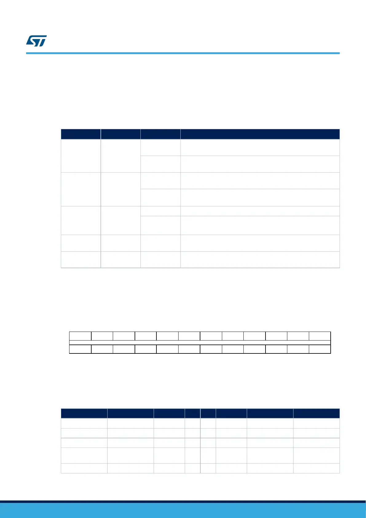
6.13.3 USB Type-C™ connector
Figure 15 shows the pinout of USB Type-C
™
connector CN15.
Figure 15. CN15 USB Type-C
™
connector pinout
GND TX1+ TX1- VBUS CC1 D+ D- SBU1 VBUS RX2- RX2+ GND
GND RX1+ RX1- VBUS SBU2 D- D+ CC2 VBUS TX2- TX2+ GND
B12 B11 B10 B9 B8 B7 B6 B5 B4 B3 B2 B1
A1 A2 A3 A4 A5 A6 A7 A8 A9 A10 A11 A12
Table 14 describes the pinout of USB Type-C
™
connector CN15.
Table 14. CN15 USB Type-C
™
connector pinout
STM32 pin Signal name Pin name Pin Pin Pin name Signal name STM32 pin
- GND GND A1 B12 GND GND -
- - TX1+ A2 B11 RX1+ - -
- - TX1- A3 B10 RX1- - -
-
VBUS_C/
5V_USB_C
VBUS A4 B9 VBUS
VBUS_C/
5V_USB_C
-
A15 UCPD_CC1 CC1 A5 B8 SBU2 - -
UM2581
USB Type-C™ FS
UM2581 - Rev 2
page 28/48

 Loading...


