-
-
-
hazard.
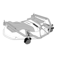
11. Take hold of the front cutting-means as-
sembly edge and lift. Continue lifting until
the cutting-means assembly is completely
vertical and rest the back end on the ground.
See g. 25.
12. Restore the cutting-means assembly to its
original position as specied in heading 5.2.3
from point 9 onwards.
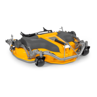
8.4 CLEANING
Always clean the bottom part of the
Take care over the sharp blades. Wear
protective gloves.
Set the cutting-means assembly to the washing
position.
Clean the bottom of the cutting-means assembly
with great care using only water and a brush.
If during use any of the paintwork has got
scratched or come o, touch up when the surfa-
ces are completely clean and dry.
Use non-perishable yellow paint for outdoor appli-
cations which is suitable for metal.
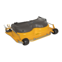
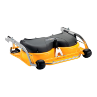
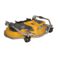
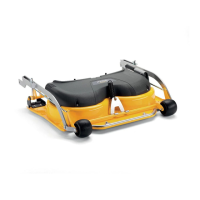
8.5 CUTTING MEANS (21:A)
8.5.1
The cutting-means assembly is tted with a
number of safety devices which reduce the risk
of damaging the cutting-means assembly and
the drive system should the same hit an obstacle
while in motion.
These devices are:
• Shear bolts (14:C) which secure the cutting
means (14:A) to the cutting means holder bar
(14:B),
• Torque limiter for cutting-means assembly drive
shaft transmission.
• possibility for positive drive belt slipping over the
plastic gearwheels.
8.5.2
Wear protective gloves.
Check that the cutting-means assembly is always
perfectly sharpened.
This is essential for obtaining optimum results.
year
an impact, replace them if damaged.
-
stance service.
same holder bar to avoid loss of correct
balance.
which can be installed on the machine,
-
ne.
Re-assemble the cutting means as follows:
• Install the cutting means (14:A) on the cutting
means holder bar (14:B) using the relative
screws (14: C and D).
• Install the cutting means hold bar on its support
(14:E).
• The cutting-means assembly can be turned
1/3 of a turn on their supports. Synchronize the
cutting-means assembly so that they are at a
90° angle to one another. See heading 7.5.3
Cutting means xing screws tightening torque:
• Screw (14:F): 45 Nm
• Screws (14:D): 45 Nm
• Shear bolts (14:C) 9.8 Nm
In the event of collision, the shear bolts (14:C) may
snap.
If this occurs, install new, genuine shear bolts and
tighten to the torque indicated.
8.5.3
The cutting-means assembly are correctly syn-
chronized when their axes are set at a 90° angle to
one another. See Fig. 21
Synchronization may be lost if the cutting means
hit an obstacle with the resulting risk of interferen-
ce.
 Loading...