EN - 8
2.
it outside the side discharge chute.
3. Fit the pin in the holes on the
and on the side discharge
chute, so that it passes through the coils
of the spring and the drilled end
4. Insert the cotter pin in the pin
hole and rotate the pin
of a pair of pliers), so it cannot slide out
and cause the pin to fall out .
Check that the spring works
correctly and keep the side discharge
chute securely lowered. Make sure that
the pin is fitted properly to prevent
it from falling out accidentally.
IMPORTANT For models with optional
side unloading: make sure that the side
unloading guard (Fig. 13.A) is lowered and
locked by the safety lever (Fig. 13.B).
IMPORTANT Before disassembling or
servicing the deector, always push the safety
lever (Fig. 14.B) and lift the side unloading
guard (Fig. 14.A) to allow disassembly.
NOTE To remove the deector, perform
assembly steps in reverse order.
4.7
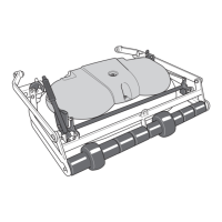
SIDE DISCHARGE MODELS
4.8
1.
2.
3.
4.
5.
6.
7.
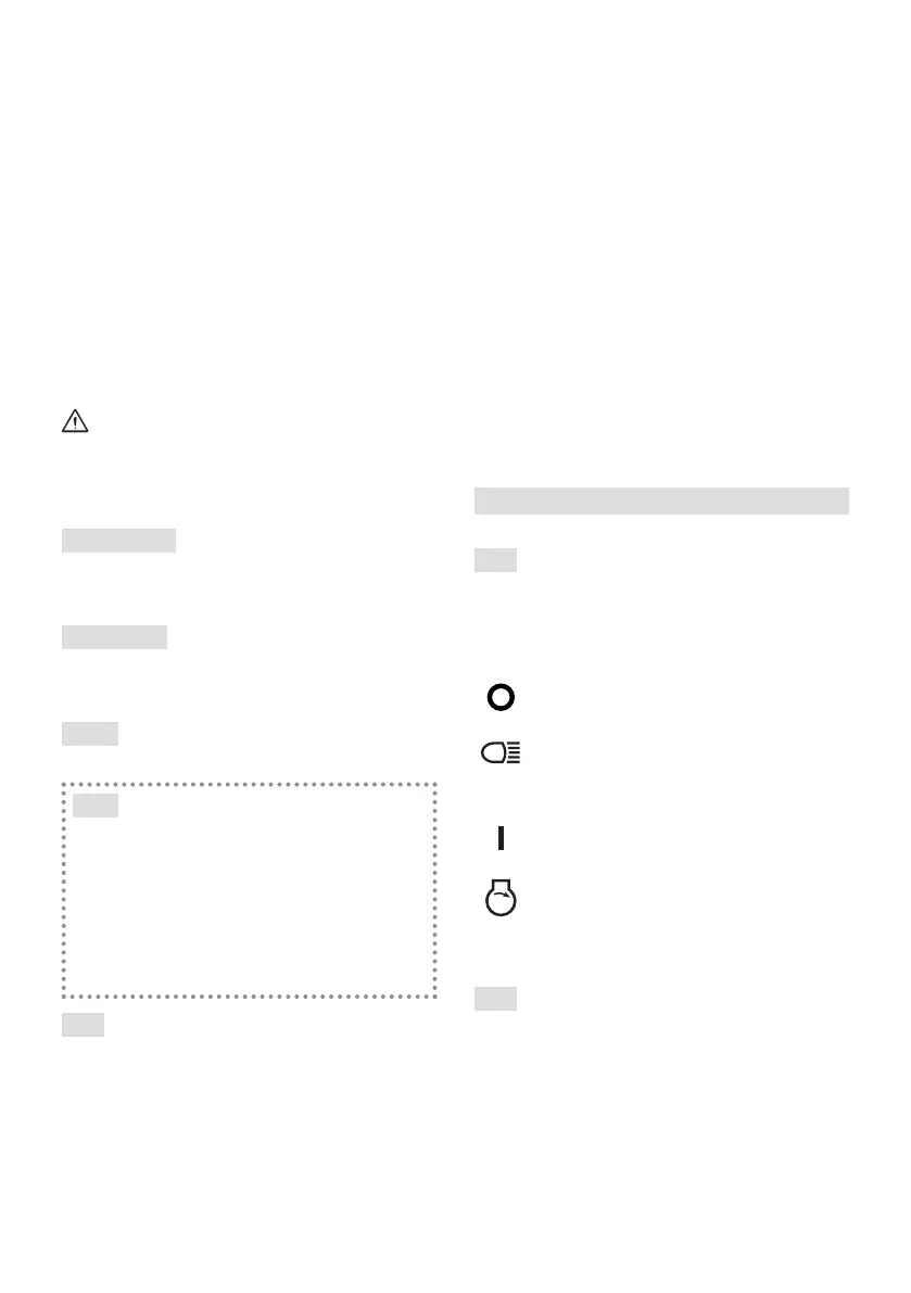
5. CONTROLS
5.1
10.A):
1. Stop position.
2. Headlights On position (if
After turning the engine
.
3. On position. All services
are enabled..
4. Start position.
5.2 THROTTLE CONTROL
A. Type “I” with separate Choke
command (Fig. 10.E + Fig. 10.E.1)
B. Type “II” (Fig. 10.E)
The positions indicated correspond to:
 Loading...