0458-507-0121-A
15
English
6 Assembling the Trimmer
► Insert and tighten down the screw (3) firmly.
The carrying ring need not be removed again.
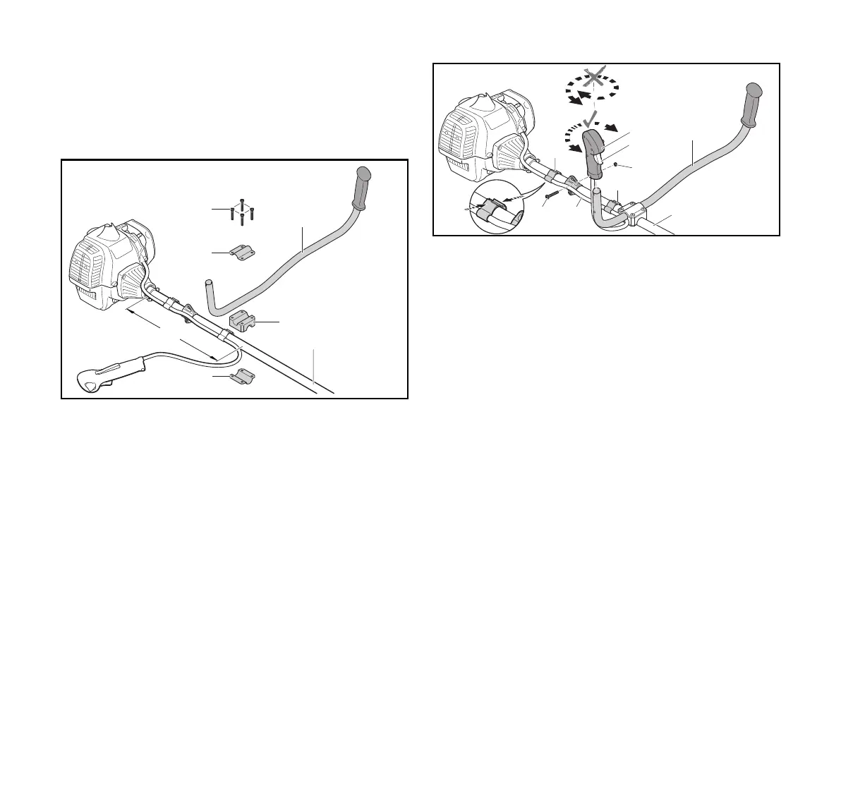
6.2 Mounting the Bike Handle
► Shut off the engine.
► Take out the screws (1).
► Fit the friction liner (4) together with the lower clamp (6) on
the drive tube (5) at distance of 35 cm (a).
► Place the handlebar (3) in the clamp (4).
► Fit the upper clamp (2) so that the holes are in alignment.
► Insert the screws (1).
► Swing the handlebar (3) up and line it up with the cutting
attachment.
► Tighten down the screws (1) firmly.
► Position the control handle (7) and throttle cable (11) over
and along the drive tube (5) – do not twist the control
handle (7).
► Take out the screw (9).
► Fit the control handle (7) on the handlebar (3), trigger
facing the gearbox, and line up the hole in the control
handle (7) with the hole in the handlebar (3).
► Fit the nut (10).
► Insert and tighten down the screw (9) firmly.
► Position the throttle cable retainer (12) and throttle
cable (11) against the drive tube.
Do not kink the throttle cable or lay it in tight radii – make
sure the throttle trigger moves freely.
► Close the throttle cable retainer (12).
The retainer (12) snaps into place.
The bike handle need not be removed again.
6.3 Mounting and Removing the Deflector
6.3.1 Mounting the Deflector
► Shut off the engine.
1
3
4
2
6
a
5
0000-GXX-7805-A1
10
12
11
12
8
7
5
3
9
0000-GXX-7806-A1
 Loading...