23Series 4144 Powerhead
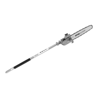
– Line up the engine pan so that
the lug (2) is on the same side as
the crankcase contour (arrow).
: Place the engine pan (1) on the
sealing face.
Press the engine pan carefully into
position so that the sealant is evenly
distributed.
: Insert the cylinder base screws
(arrows) in the holes to hold the
engine pan in position.
938RA054 TG
1
2
938RA055 TG
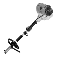
– Prepare the puller (1) 5910 890
4400.
: Fit the No. 2 jaws (2) 0000 893
3700.
: Screw the bushing (3) 1108 893
4500 onto the puller's spindle.
Take care not to damage the
crankshaft stub.
: Apply the puller (1) 5910 890
4400 with the jaws under the
crankcase ribs (arrows) and line
up the spindle (2) so that the
bushing (3) is centered on the
engine pan.
: Turn the spindle (2) clockwise
until the puller sits tightly.
Do not overtighten the spindle
because the jaws may slip off or
damage the crankcase ribs.
296RA033 TG
2
3
1
1
2
3
938RA056 TG
– Install the cylinder, b 6.4
– Tightening torques, b 3.3
– Remove the puller.
– Clean the crankshaft stubs, b 9
– Install the engine – see service
manual for "Series 4144
Components – FS, FC, KM"
– Reassemble all other parts in the
reverse sequence.
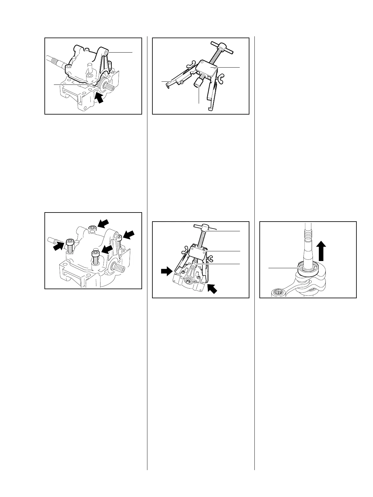
6.6 Bearings / Crankshaft
– Remove the crankshaft, b 6.5.1
– Pull off the oil seals, b 6.5.1
: Pull the ball bearing (1) off the
tapered crankshaft stub.
938RA057 TG
1
 Loading...