28 Series 4144 Powerhead
7.1 Ignition Module
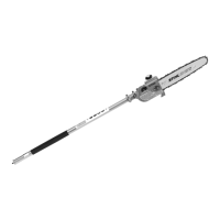
The ignition module accommodates
all the components required to
control ignition timing. There are
two electrical connections on the
coil body:
– High voltage output (1) with
ignition lead
– Connector tag (2) for the short
circuit wire
Testing in the workshop is limited to
a spark test. A new ignition module
must be installed if no ignition spark
is obtained (after checking that
wiring, stop switch and flywheel are
in good condition), b 7.1.1.
Ignition timing is fixed and cannot
be adjusted during repair work.
Since there is no mechanical wear
in these systems, ignition timing
cannot get out of adjustment during
operation.
938RA077 TG
2
1
7.1.1 Removing and Installing
– Remove the engine – see service
manual for "Series 4144
Components – FS, FC, KM"
The air gap between the ignition
module and flywheel can be
adjusted only when the engine is
removed.
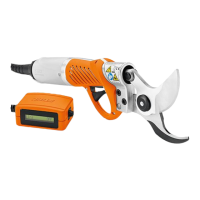
: Pull boot (1) off the spark plug.
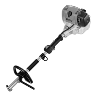
: Disconnect the short circuit
wire (1).
: Take out the screws with
washers (arrows).
545RA008 TG
1
1
938RA078 TG
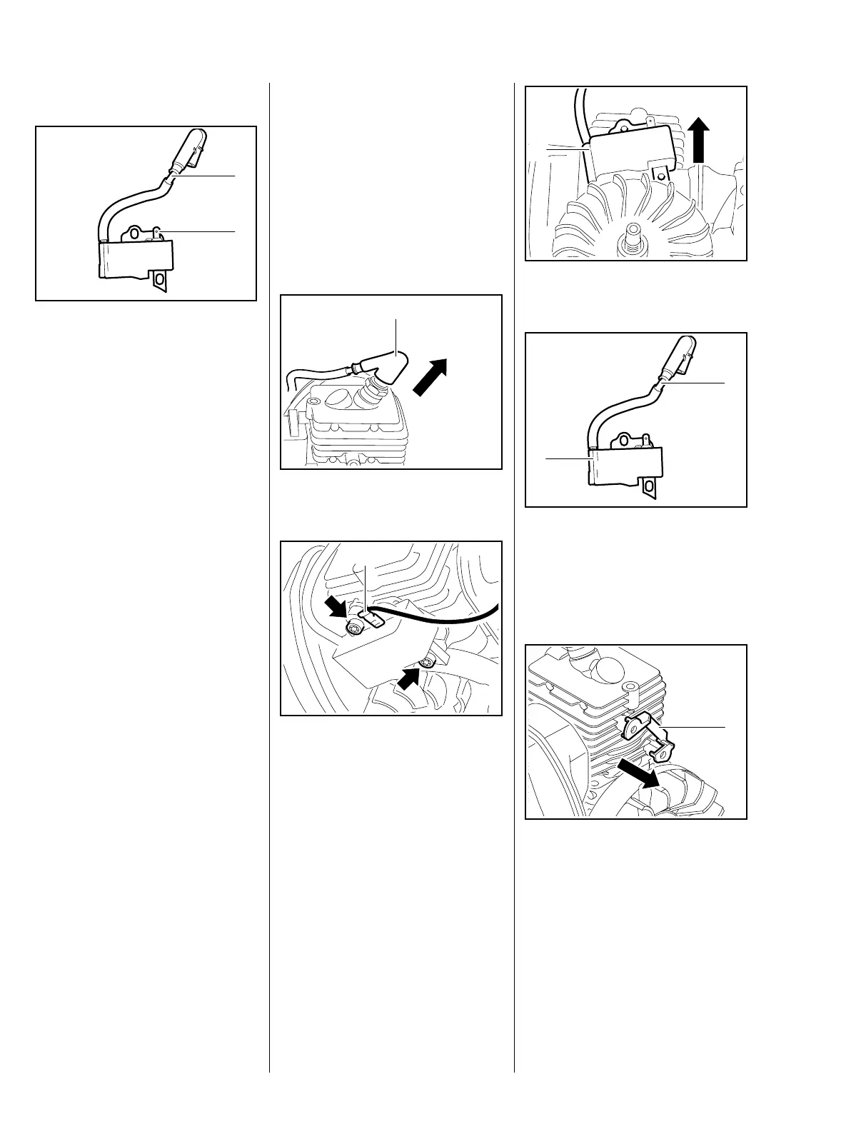
: Remove the ignition module (1).
The ignition module (1) and ignition
lead (2) form a unit.
– Check the ignition module (1) and
lead (2), and replace if necessary
: Remove the insulator (1).
– Check the insulator and replace if
necessary.
– Check the spark plug boot and
replace if necessary, b 7.4
– Troubleshooting, b 4.2
1
938RA079 TG
938RA080 TG
2
1
1
938RA081 TG
 Loading...