0458-805-8621-A
4
English
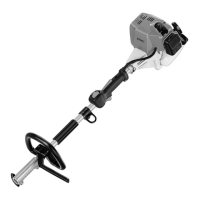
4 Main Parts
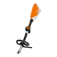
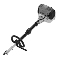
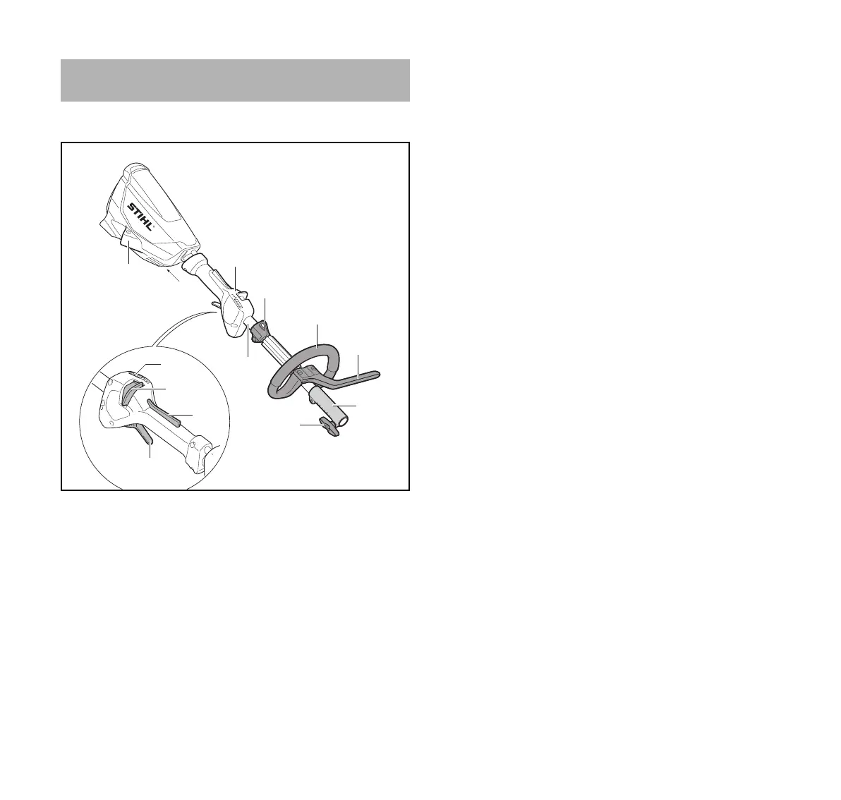
4.1 KombiMotor
1 Socket
Socket for the plug of the battery connecting cord.
2 Control Handle
Handle for the operator's rear hand.
3LEDs
Indicate the unit's power level.
4 Retaining Latch
Locks / unlocks the trigger switch. Sets the unit's power
level when it is in active mode.
5 Trigger Switch Lockout
Must be depressed while the retaining latch is unlocked
to allow activation of the trigger switch.
6 Trigger Switch
Controls the activation and speed of the KombiMotor.
7 Carrying Ring
For connecting a harness to the power tool.
8Drive Tube
Shaft of the KombiMotor.
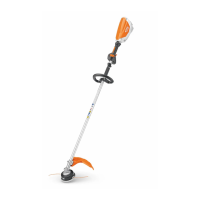
9 Loop Handle
Handle for the operator's front hand.
10 Barrier Bar
Designed to reduce the risk of inadvertent operator
contact with the cutting/working attachment.
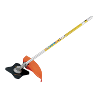
11 Coupling Sleeve
Connects the KombiMotor to the KombiTool (stub shaft).
12 Wing Screw
Secures the KombiTool (stub shaft) to the KombiMotor.
# Rating Plate
Contains electrical information and the product's serial
number.
4Main Parts
1
2
7
9
10
12
11
#
3
4
5
6
8
0000-GXX-4641-A0
 Loading...