Troubleshooting Guides
600 Series
(Prior to #1810000)
8-16
#3756270 - Revision B - January, 2006
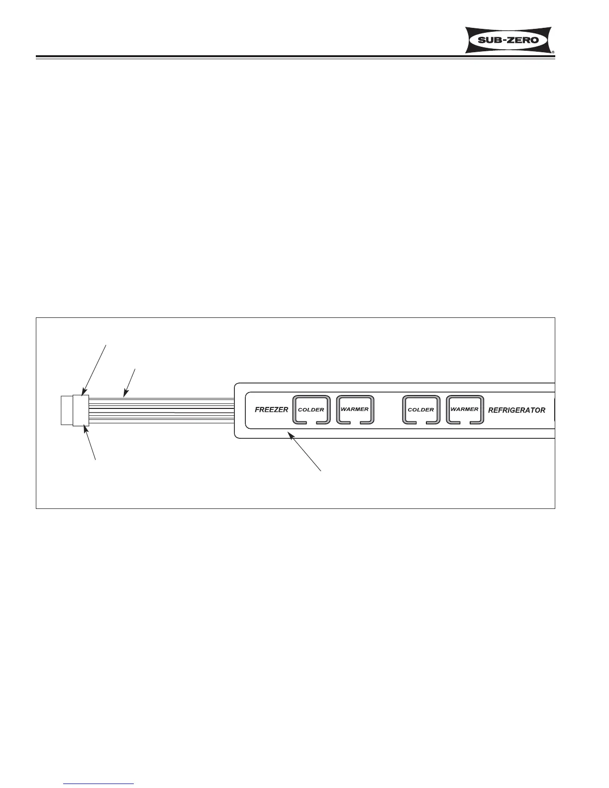
Pin #1 at top
Ribbon Cable
Membrane Switch in
Control Panel
Exposed points/pins on
back side of housing
Figure 9-1. Membrane Switch
MEMBRANE SWITCH/RIBBON CABLE TESTS
Below is the procedure to follow if the integrity of the membrane switch on the control panel is suspect. To perform
these tests, the ribbon cable terminal housing must be disconnected from the control board.
NOTE: The wires of the ribbon cable are exposed at the back side of the terminal housing. With an Ohm Meter,
check for continuity at these exposed points/pins. Pin #1 is at the top of the terminal housing, closest to the arrow on
the housing (see Figure 9-1).
1. Without pressing any of the keys on the membrane switch, check for continuity across all pin combinations. With
no keys pressed, there should be no continuity.
2. With the UNIT ON/OFF key depressed, there should be continuity across pins #1 & #5 only.
3. With the Freezer COLDER key depressed, there should be continuity across pins #1 & #2 only.
4. With the Freezer WARMER key depressed, there should be continuity across pins #2 & #3 only.
5. With the Refrigerator COLDER key depressed, there should be continuity across pins #1 & #3 only.
6. With the Refrigerator WARMER key depressed, there should be continuity across pins #3 & #4 only.
7. With the ICE ON/OFF key depressed, there should be continuity across pins #1 & #4 only.
NOTE: If the membrane switch fails any of the fore mentioned tests, the control panel should be replaced.
 Loading...