Component Access / Removal
600 Series
(Prior to #1810000)
7-39
#3756270 - Revision B - January, 2006
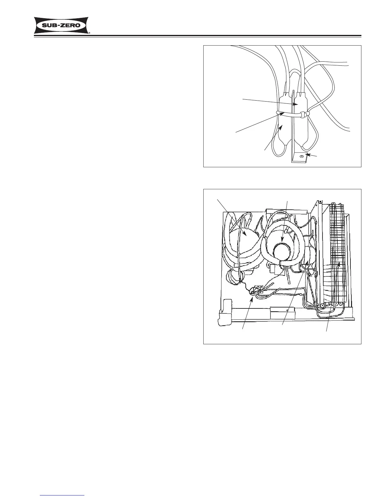
Figure 7-70. Models 611, 632, 642, 650, 690 Filter-Drier
Location & Position
Freezer Filter-Drier
Refrigerator
Filter-Drier
Figure 7-71. Models 611, 632, 642, 650, 690 Upper
Compressor Area
Cable Tie
Drier Bracket
Freezer Compressor
Refrigerator Compressor
Filter-Driers
Condenser
Condenser Fan
Filter-Drier (Models 611, 632, 642, 650, 690)
Filter-driers are secured to a bracket in the compressor
area by a cable tie. (See Figures 7-70 & 7-71) To
remove a filter-drier, after capturing the refrigerant from
the sealed system, use a file to score a line around the
capillary tube approximately one inch from the drier out-
let. Fatigue the capillary tube at this line until it sepa-
rates. Then, with a tube cutter, cut the drier inlet tube.
NOTE: Check the end of the remaining capillary tube
for internal burrs. If burrs exist, re-score capillary tube
approximately one inch from end. Then, fatigue capil-
lary tube at this new line until it separates, and recheck.
NOTE: When installing the replacement filter-drier,
insert capillary tube until it touches the screen. Then,
pull capillary tube away from the screen approximately
3/8" before brazing.
NOTE: The filter-drier outlet must be facing downward
in order to function properly. (See Figure 7-70)
Compressor (Models 611, 632, 642, 650, 690)
NOTE: When replacing a compressor, the filter-drier
must be replaced.
NOTE: Compressor and tubing may be hot and could
cause minor personal injury.
The compressors are secured to the top of the unit with
nuts over stud-bolts. The left compressor is the freezer
compressor, and the right is the refrigerator compres-
sor. (See Figure 7-71) To remove a compressor, the
unit grille and compressor baffle must first be removed.
Then, remove the screws which secures the drier
bracket to the top of the unit so that the bracket may be
easily shifted during compressor removal. After captur-
ing the refrigerant from the sealed system, remove the
compressor electrical cover and disconnect the electri-
cals from the compressor. Now, remove the nuts from
the stud-bolts at each corner of the compressor base.
Lift the compressor until it clears the stud-bolts and pull
it forward slightly to gain better access to the suction
and discharge lines. Using a tube cutter, cut the suc-
tion and discharge lines approximately one inch from
the compressor, then pull compressor out.
Condenser Removal
(Models 611, 632, 642, 650, 690)
NOTE: When replacing the condenser, both filter-driers
must be replaced.
NOTE: Evaporator fins are sharp and could cause
minor personal injury.
To remove a condenser, the unit grille and compressor
baffle must be removed first. Then, after capturing the
refrigerant from the sealed system, pull the unit from its
installation (see WARNING above), and remove the unit
shroud. Now, remove the screws which secure the
condenser fan shroud to the condenser, and un-braze
or cut the condenser inlet and outlet tubing. Then,
extract the mounting screws which secure the con-
denser side brackets to the top of the unit, and lift con-
denser off. (See Figure 7-71)
 Loading...