26
DIAGNOSTIC SYSTEM
If abnormal conditions exist in any sensor sig-
nal being input to the control unit, the self-diag-
nostic system warns of the abnormal condition.
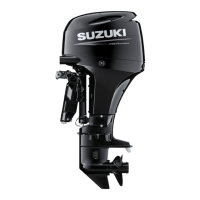
If this system activates, the red CHECK
ENGINE lamp will flash and a buzzer will
sound.
Also incorporated is a fail-safe provision that
allows the operation at a restricted speed even
under such a failure condition.
The failed system can be identified by the mode
of the lamp flashing and buzzer sounding.
The diagnostic code is designed to appear
when the ignition key is turned on.
NOTE:
Remote control model:
The buzzer sound with diagnostic system acti-
vating will be canceled by pushing the ignition
key in.
NOTICE
If the diagnostic system activates while you
are operating your outboard motor, there is an
abnormal condition in one of the sensor sig-
nals of the control system.
Consult your authorized Suzuki marine dealer
for repair of the control system.
Tiller handle model Remote control model
OIL CHANGE REMINDER
SYSTEM
This system informs the operator of the time for
replacing engine oil on the basis of the mainte-
nance schedule.
The system is designed to register the total
operating hours of the outboard motor and
function its operation when the preprogrammed
hours have reached.
(Refer to the INSPECTION AND MAINTE-
NANCE section and the last page.)
SYSTEM ACTIVATION
When the total operating hours have reached
the preprogrammed hours, the OIL lamp will
flash. If the engine is not running, the buzzer
will begin a series of double beeps additionally.
This indication will repeat until you cancel the
system activation.
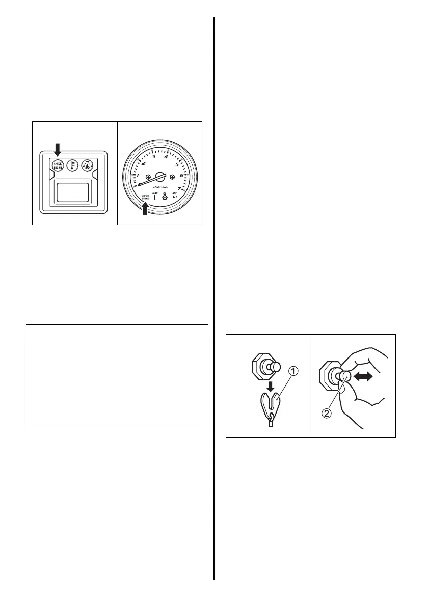
CANCELLATION
1. Turn the ignition key to the “ON” position.
2. Pull out the emergency stop switch plate 1.
3. Pull up the emergency stop switch knob 2
three times in 10 seconds. A short beep will
be heard if the cancellation is successfully
finished.
4. Turn the ignition key to the “OFF” position.
5. Set the plate 1 in the original position.
 Loading...