 Loading...
Do you have a question about the Suzuki M109R and is the answer not in the manual?
| Displacement | 1783 cc |
|---|---|
| Bore x Stroke | 112.0 mm x 90.5 mm |
| Compression Ratio | 10.5:1 |
| Fuel System | Fuel injection |
| Ignition | Electronic ignition (transistorized) |
| Starter | Electric |
| Transmission | 5-speed constant mesh |
| Final Drive | Shaft drive |
| Front Suspension | Inverted telescopic, coil spring, oil damped |
| Rear Suspension | Link type, coil spring, oil damped |
| Rear Brakes | Single hydraulic disc |
| Rear Tires | 240/40R18M/C 79V, tubeless |
| Ground Clearance | 140 mm (5.5 in) |
| Seat Height | 705 mm (27.8 in) |
| Engine Type | 4-stroke, liquid-cooled, DOHC, V-twin |
| Front Brakes | Dual hydraulic disc |
| Front Tires | 130/70R18M/C 63H |
| Overall Length | 2, 480 mm |
| Overall Width | 875 mm |
| Overall Height | 1, 130 mm |
| Wheelbase | 1, 710 mm |
| Curb Weight | 347 kg |
Position motorcycle on a jack or kickstand for right-side access.
Using a jack enables spinning the rear wheel for later steps.
Instructions for removing the exhaust system are available via a provided link.
Identify and record each bolt and its position during removal for correct reinstallation.
Be aware of the number of bolts with washers and their specific placement to prevent oil leaks.
Apply appropriate torque (10-14 ft lbs) when retightening bolts to avoid stripping threads or breaking bolts.
Gently tap the side cover with a rubber mallet to loosen it.
Avoid ripping the gasket during cover removal; use a screwdriver slowly and carefully.
The gasket can usually be reused if undamaged; replace if necessary.
Cleanliness of the cover and gasket is crucial for preventing oil leaks upon reinstallation.
With the transmission in gear, spin the rear wheel to verify the primary drive gear spins freely.
If the primary drive gear does not spin freely, move to the next step.
Unscrew the six 10mm bolts and remove the springs.
Take out the clutch pressure disc and examine it for any damage.
When retightening, use caution (6-8 ft lbs) to avoid stripping threads.
Spin the rear wheel to confirm the primary drive gear rotates unimpeded.
Push the clutch push piece and pull the clutch lever to observe movement.
The clutch push piece should move approximately 1/4 inch when the clutch lever is pulled.
Remove the clutch push piece by gently pulling it out.
Locate and identify the washers and bearing present in this assembly.
Carefully inspect all removed components for wear or damage.
Clean and inspect each clutch drive plate, noting their original order and position.
It is advisable to order any damaged or worn clutch drive plates at this stage.
Pry/tap the nut notch to original shape or use an impact gun for removal.
Reinstall the nut and tighten to approximately 80 ft lbs, re-notching it to lock.
Take out the clutch hub and examine it for cleanliness and any damage.
Spin the rear wheel to confirm the primary drive gear spins freely.
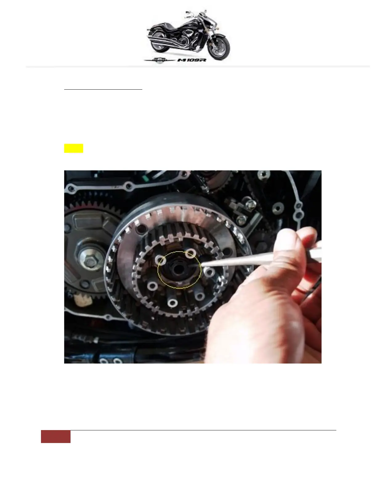
Examine the nut in the center of the primary drive gear for looseness.
If the nut can be turned by hand, it indicates a significant problem.
Remove the tubular nut and inspect it for any issues.
A Honda Socket/Spanner for the VTX is recommended for the tubular nut.
Clean the tubular nut using electrical contact cleaner or a residue-free solvent.
Apply RED Loctite when installing the tubular nut.
Tighten the tubular nut to a torque of 100-105 ft lbs.
Install the first clutch plate, part #6 21441-48G10; direction does not matter.
Install the second item, washer #13 21472-48G00; direction is not critical.
Install the third item, seat, wave washer #12 21471-48G00, with debated orientation.
Install the fourth clutch plate, part #10 21441-48G00.
Install the fifth clutch plate, part #5 21451-48G00.
Install the sixth clutch plate, part #9 21441-48G00.
Install the seventh clutch plate, part #5 21451-48G00.
Install the eighth clutch plate, part #9 21441-48G00.
Install the ninth clutch plate, part #5 21451-48G00.
Install the tenth clutch plate, part #9 21441-48G00.
Install the eleventh clutch plate, part #5 21451-48G00.
Install the twelfth clutch plate, part #9 21441-48G00.
Install the thirteenth clutch plate, part #5 21451-48G00.
Install the final clutch plate, #10 21451-48G10, ensuring it faces away from the bike.