Electrical connection |
9
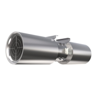
Table 5 Description of electrical connections of the following fans: AW 630D EC sileo (#35872), AW 710D-L EC sileo
(#35876), AW 800D EC sileo (#35879), AW 1000D EC sileo (#35899)
Wire
no.
Connection
Function/assignment
PE PE
Protective conductor
1 L1
KL1
Power supply, see name plate for voltage range
2 L2
3 L3
3 NC
KL2
Status relais, open for failure
2 COM
Status relais, changeover contact, common connection (2 A, max. 250
VAC, min. 10 mA, AC1)
1 NO
Status relais, close for failure
1 RSB
KL3
RS485 interface for MODBUS
2 RSA
RS485 interface for MODBUS
3/10
GND
GND-connection of the controller interface
4 Ain1 U
Analog input 1, set value: 0-10 V, Ri = 100 kΩ, adjustable curve, only
usable as alternative to input Ain1 I; SELV
5 +10 V
Fixed voltage output 10 VDC, +10 V ±3%, max. 10 mA, short-circuit-
proof power supply for external devices (e.g. pot); SELV
6 Ain1 I
Analog input 1, set value: 4-20 mA, Ri = 100 Ω, adjustable curve, only
usable as alternative to input Ain1U; SELV
7 Din1
Digital input 1: enable electronics
enable: pin open or applied voltage 5-50 VDC
disable: bridge to GND or applied voltage < 1 VDC
reset function: triggers software reset after a level change to < 1 VDC;
SELV
8 DIN2
Digital input 2: Switching parameter sets 1/2, according to EEPROM
setting, the valid or used parameter set can be selected via bus or via
digital input DIN2.
Parameter set 1: pin open or applied voltage 5-50 VDC
Parameter set 2: bridge to GND or applied voltage < 1 VDC; SELV
9 DIN3
Digital input 3: according to EEPROM setting, the integrated controller's
direction of action can be selected as normal/inverse via bus or digital
Input normal: pin open or applied voltage 5-50 VDC
Input inverse: bridge to GND or applied voltage < 1 VDC; SELV
11 Ain2 U
Analog input 2, measured value: 0-10 V, Ri = 100 kΩ, adjustable curve,
only usable as alternative to input Ain2I; SELV
12 +20 V
Fixed voltage output 20 VDC, +20 V +25/-10%, max. 50 mA, short-
circuit-proof power supply for external devices (e.g. sensors); SELV
13 Ain2 I
Analog input 2, measured value: 4-20 mA, Ri = 100 Ω, adjustable curve,
only usable as alternative to input Ain2U; SELV
14 Aout
Analog output, 0-10 VDC, max. 5 mA, SELV output of current motor
modulation level:
1 V corresponds to 10% modulation level.
10 V corresponds to 100% modulation level.
8.4 Protective grounding wire
The protective grounding must have a cross-section equal to or greater than that of the phase conductor.
8.5 Residual current circuit breaker
All-current-sensitive residual current circuit breakers are required for use in alternating-current systems with 50/60 Hz,
in combination with electronic devices such as EC motors, frequency converters or uninterruptible power supplies
(UPS).
| 003
 Loading...
