RS EC RSI EC 1–phase 230 V
RS 30–15 EC RSI 60–35 EC
N
N L
L 1 2 3 4
BU
BU
RD
WH
YE
BK/BN
GY
RS 40–20 EC RSI 70–40 EC
RS 50–25 EC
RS 60–35 EC
RS 70–40 EC
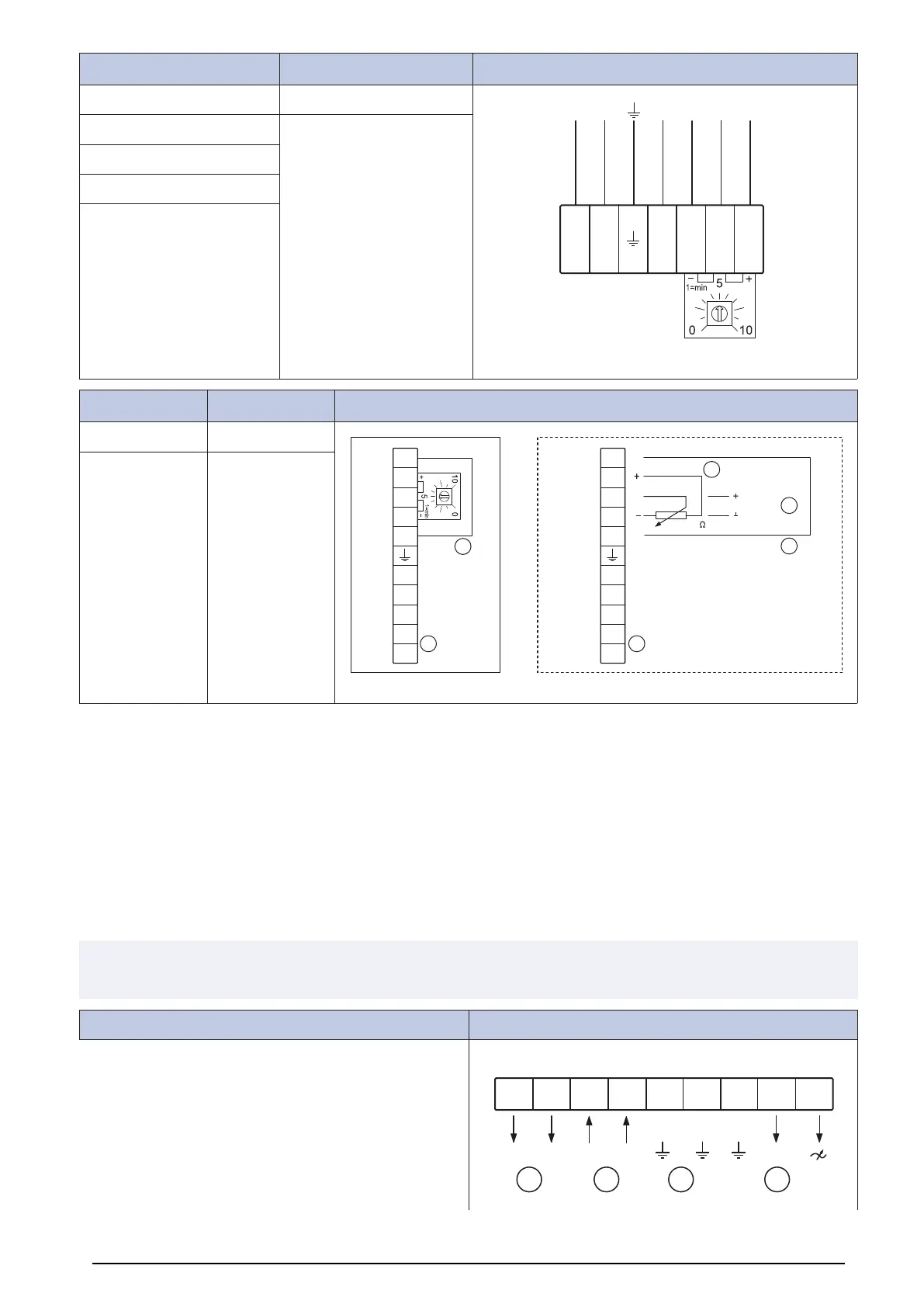
RS EC
RSI EC
3–phase 400 V
RS 80–50 EC RSI 80–50 EC
GND
E1
10V
D1
24V
L3
L1
L2
11
14
GND
10k
0-10V DC
E1
E1
10V
D1
24V
L3
L1
L2
11
14
D
A A
D
B
C
RS 100–50 EC RSI 100–50 EC
A. 11 & 14 = Alarm
For operation: the relay is energized, connections 11 and 14 are bridged
For fault: the relay is de-energized (diagnostics/faults)
Contact rating maximum AC 250 V 2 A
B. External potentiometer
C. External input DC 0...10 V
D. External ON/OFF control through potential free contact
12.3.3 Wiring diagrams for speed controller for AC motors
Note:
The selection of electrical accessories must be done in line with the technical parameters of the product.
RE
Manual 5-step transformer.
RE 1,5
N N N
RE 3 RE 5 RE 7
~ ~
DCBA
20
 Loading...