English
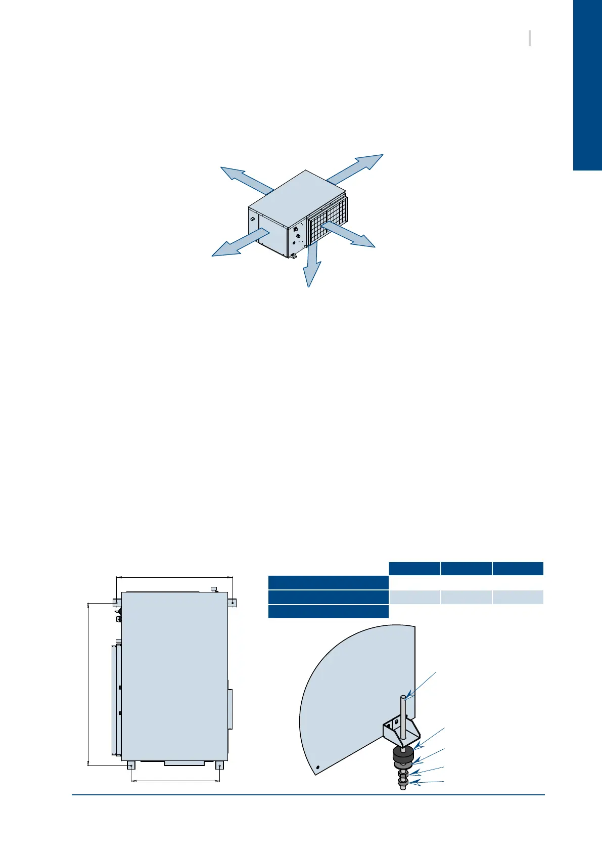
600 mm
200 mm
600 mm
600 mm
600 mm
M8 THREADED ROD
(NOT SUPPLIED)
SHOCK MOUNT
WASHER
NUT
LOCKNUT
9SYSHRW
9. INSTALLATION
9.1. UNIT LOCATION
1. Install the unit in a location allowing easy removal of the lter and the access panels to the electrical
box/compressor and fan by leaving sufcient free space for servicing personnel to perform
maintenance and repairs. Leave sufcient space for the water, electricity and duct connections.
2. The installer must ensure that access under the suspended ceiling is provided, and that sufcient
space is provided for the suspension angle brackets, the duct attachment collars and the water and
electrical connections.
3. Provide space under the unit for a siphon on the condensates drainage pipe. Do not install the unit
on top of pipe work.
4. Each unit is suspended from the ceiling on four threaded rods. The rods are attached through the
shock mounts to the corners of the unit by suspension angle brackets.
Warning! Do not use rods of a diameter smaller than that stated below. The rods must be solidly
anchored to the ceiling and to the ceiling joists.
5. Each unit is supplied with a set of pre-tted suspension angle brackets and a tting kit contained in
the pouch with the technical manual. The kit comprises 4 shock mounts, 4 washers, 4 nuts and 4
locknuts.
6. Arrange the threaded rods in accordance with the dimensions stated below. The use of nuts and
locknuts is recommended for attaching the suspension rods to the unit as the unit’s vibrations may
loosen a single nut. The installer is liable for any damage in the event of this recommendation not
being followed.
7. To facilitate drainage, the unit must be angled in both planes towards the condensates drainage pipe.
A B C
19
662 843 510
27-30-36
724 1015 551
42-48-60-72
769 1215 596
 Loading...


