English
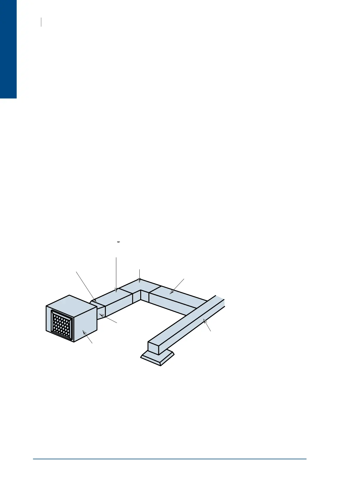
Internal cladding on both sides
with glass fibre sound insulation
Adapter part
Alignment elbow
Main duct
Spur with internal glass fibre
sound insulation cladding
Air distributor:
60 x 60 cm (example)
Canvas
connection
Heat pump
10 SYSHRW
10. DUCTING AND NOISE LEVEL REDUCTION
Water circuit heat pumps are usually installed in conjunction with an air blowing duct. A return air duct may
also be required. All ductwork shall be compliant with best air conditioning engineering practices.
The air blowing duct system normally consists of a exible connector mounted on the unit, a bridging section
to link to the size of the main duct, a short section of straight duct, an elbow without a damper and a main
duct with spurs equipped with distribution grilles as illustrated in the drawing below. The sum total of the
bridging section angles must not be higher than 30°, otherwise there will be signicant performance losses.
Do not connect the main duct directly to the unit without a bridging section to reduce the duct size to that of
the unit’s connection collar. In the event of using metal ducts, only the sides of the elbow section and all the
spur duct sections should be covered with breglass sound insulation for reducing the noise level. Fibreglass
duct panels are more sound absorbent and may enable the exible canvas connection to be eliminated.
The duct network must be laid out to avoid any rectilinear runs betweens the heat pump outlet and the air
distribution outlets.
The return air intake ducts can be connected to a grille/lter located at the base of a wall, then directed via
hollow partitions towards a ceiling mounted plenum or via ceiling mounted grilles. The ceiling grilles must
not be located directly below the air conditioning unit.
The return air intake duct can be connected directly to the standard lter bracket. (Lateral lter removal
advisable).
Do not drill panel screws directly into the unit’s casing for connecting the blowing and return air intake ducts,
especially on the air return side, as there is a risk of damaging the condensate recovery tray and the battery.
Recommended layout diagram for installation
with several air distribution outlets
 Loading...


