English
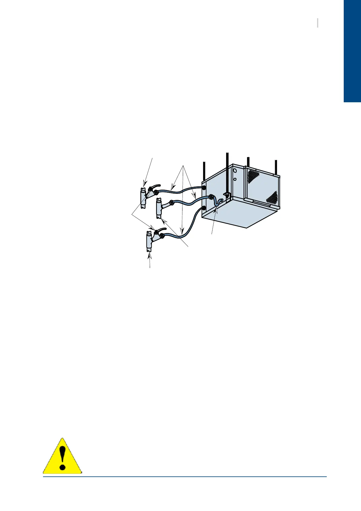
Main return
pipe work
Hoses
Spherical
dome valve
Siphon
Main condensate
drainage pipe work
Main water supply
pipe work
15SYSHRW
11. HYDRAULIC CONNECTIONS
11.1. RECOMMENDATIONS FOR HYDRAULIC CONNECTIONS
1. t is recommended that all units are connected to a water supply and return pipe system of the
Tickelman Loop type. The Tickelman Loop system is self-balancing and thus only requires manual
balancing if a large number of units with different ow and pressure loss characteristics are
connected to a single hydraulic loop. A very simple way of checking the hydraulic balance is to
measure the temperature difference between the water connections. To ensure a correct water ow,
the difference must be in the region of 3 to 7 °C in Cooling mode and 2 to 5°C in Heating mode.
A system with two parallel pipes can also operate in a perfectly adequate manner, but it is more
difcult to achieve, and to maintain, balance.
2. Steel, copper or P.V.C. pressure pipes may be used.
3. It is advisable to make the unit’s water supply and return conveyance lines with short lengths of
high-pressure hose, as they form excellent shock absorbers for unit operating noise and hydraulic
pressure surges.
One of the hose ends must be tted with a rotating connector to facilitate removal for maintenance.
Rigid pipes can be connected directly to the unit, but this is not recommended due to their inability to
absorb vibrations and noise.
Rigid pipes must be equipped with removable connectors to facilitate future removal of the unit from
its location.
4. Certain exible hose threaded connectors are supplied with sealing paste. If this is not the case, use
Teon tape to create a tight seal.
5. Each unit must be equipped with isolation valves on the water inlet and outlet pipes. The return
isolation valve is used for both cutting off the water supply and balancing the installation’s water
ow. As it is used to establish the balance of the ows, it must be equipped with a lockable position
end stop. This end stop ensures that, after the valve is closed, it can only be re-opened as far as the
position required to maintain a balanced water ow.
6. Never connect a unit to the water supply and return lines without completely cleaning and
flushing out the hydraulic loop beforehand. After performing these operations, the units must be
connected, with all valves completely open, ready for the system to be lled with water.
COMMENT: In order to limit clogging the plate heat exchanger and to optimise unit
operation, it is advisable to equip the system with a sieve lter (Ø 0.8 mm) on the unit
water inlet pipe work. This lter should be installed between two isolation valves and
should remain accessible to the user for periodic checks.
 Loading...


