EasyManua.ls Logo

SystemAir TA 2000 HW User Manual

SystemAir TA 2000 HW
30 pages
To Next Page IconTo Next Page
To Previous Page IconTo Previous Page
Page #27 background image
8.3Installation
1
Findanappropriateplacetoinstallthecontrolpanel.Maximumlengthbetweencontrolpaneland
unitis100m.
2
Ifneeded,drilltwoholesinthewalltohangthecontrolpanel(centertocenter:60mm)(pos.1,gure13).
Fig.13Controlpanelwireconnections
PositionDescription
1Mountingholes
2
Connectionblock
3
Connectiontobrowncable
4
Connectiontoyellowcable
5
Connectiontowhitecable
6
Connectiontoblackcable
TA450-4500Installationinstructions
132615
25
SystemairSverigeAB
Question and Answer IconNeed help?

Do you have a question about the SystemAir TA 2000 HW and is the answer not in the manual?

SystemAir TA 2000 HW Specifications

General IconGeneral
Airflow2000 m³/h
Supply voltage230V
Phase1~
Frequency50Hz
Max. operating temperature40°C
Protection classIP44
Heating coilHot water

Summary

Warnings

Installation

Where/How to Install

Guidance on selecting the installation location and necessary space for operation and maintenance.

Installing the Unit

Instructions and considerations for physically mounting the air handling unit.

Ducting

Recommendations for designing and installing duct systems for optimal performance and cleaning.

Duct Connections

Steps for securely connecting ductwork to the unit, ensuring air tightness.

Electrical Connections

TA 450-1400 EL

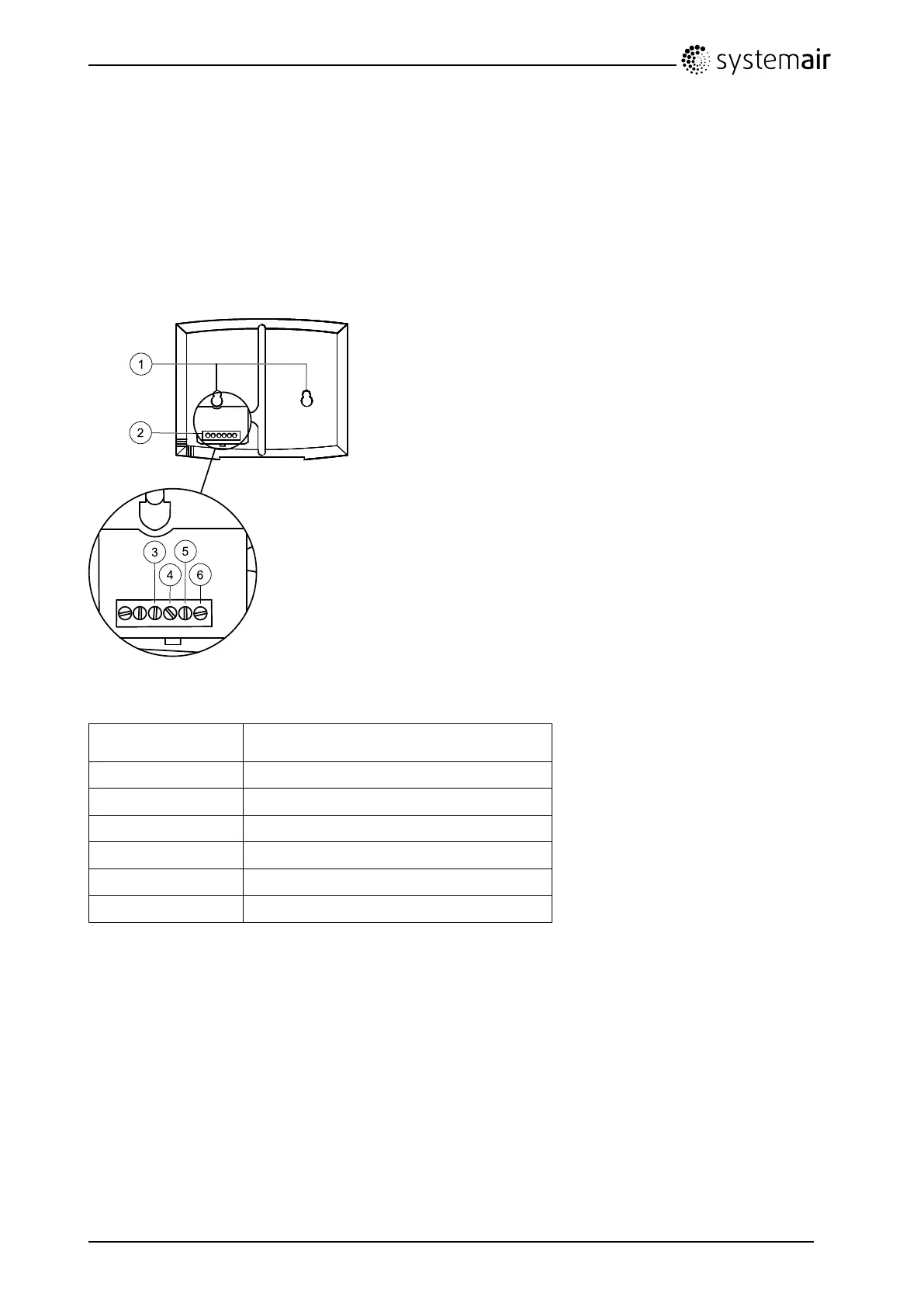
Detailed terminal block wiring configurations for TA 450-1400 EL models.

TA 2000 EL

Detailed terminal block wiring configurations for TA 2000 EL models.

TA 1400 HW

Detailed terminal block wiring configurations for TA 1400 HW models.

TA 2000-4500 HW

Detailed terminal block wiring configurations for TA 2000-4500 HW models.

Changing Fan Speed

BMS Connection

Control Panel

Installation

Instructions for selecting a location and mounting the control panel.

Before Starting the System

Related product manuals