4
| Product description
2.3 Description of internal components
2.3.1 Supply and extract air fans
The fans have external rotor motors of EC type which are steplessly controlled individually by setting the control signal
to a fixed value. It is possible to program the speed in 2 steps (normal/reduced) depending on the programming of the
week schedule. The motor bearings are life time lubricated and maintenance free. It is possible to remove the fans for
cleaning, see chapter 5 for more information.
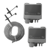
2.3.2 Pressure sensor fans
2 pressure sensors maintain the airflow at a constant level by measuring the differential pressure over the inlet cone of
the fan impellers (pos.10 figure 1, pos.10 figure 2). The pressure sensors are installed from factory in all CAV units. VAV
control of the fans is available as an accessory. The VAV accessory kit includes two pressure sensors, tubes, electrical
cables and instruction on how to connect to the air handling unit and set-up the controller. See also “Installation instruc-
tions” for more information concerning VAV installations.
2.3.3 Supply and extract air filters
The filters are of bag filter type with filter quality F7 for the supply air filter and F5 for the extract air filter. The filters
need to be replaced when polluted. New sets of filters can be acquired from your installer or wholesaler.
2.3.4 Pressure guard for filters
A pressure guard measures the differential pressure over the supply and extract air filters (pos.9 figure 1,figure 2).
When the pressure drop reaches the set value an alarm is triggered in the main regulator. The differential pressure can
be set between 40 and 300 Pa. The pressure switch is preset from factory to 240 Pa.
2.3.5 Heat exchanger
Topvex SR/TR models are equipped with a highly efficient, belt driven, rotating aluminium heat exchanger. Required
supply air temperature is therefore normally maintained without adding additional heat. The operation of the heat ex-
changer is automatic and depends on the set temperature. An extra driving belt is included on the rotor on delivery
(pos. 8 figure 1 and figure 2).
The heat exchanger is removable for cleaning and maintenance, see chapter 5 for more information.
2.3.6 Rotor motor
The rotor motor drives the exchanger rotor with a variable rpm as long as there is a heat demand. The motor is con-
trolled by an analogue 0-10V control signal (figure 1 and figure 2).
2.3.7 Rotation guard
A sensor registers the rotation of the heat exchanger rotor. It’s connected by the rotor to the main regulator which
gives an alarm if the rotor stops while there is a heat demand (pos.7 figure 1 and figure 2).
2.3.8 Temperature sensors
4 temperature sensors (PT1000) are included in the unit from factory:
• Supply air sensor
• Extract air sensor
• Outdoor air sensor
• Exhaust air sensor
In Topvex TR 03-06 all temperature sensors are mounted and wired inside the unit. In Topvex SR 03-06 the supply air
sensor is loosely delivered with the unit and needs to be installed in the supply air duct externally from the unit. See In-
stallation instructions for more detailed information.
2.3.9 Water heating battery
In units with built in water heating battery the hot water coil is located next to the supply air connection. The hot water
coil can be either HWL (hot water coil, low power) or HWH (hot water coil, high power). The coil material is copper pip-
ing with a frame of galvanized sheet steel and aluminium fins. The coil is equipped with venting and immersion sensor
for frost protection.
 Loading...