11
5.2 Drain test
1. Before testing, ensure that water can drained well and check all
joints are sealed.
2. The drainage test must be done before constructing the ceiling
of a new house.
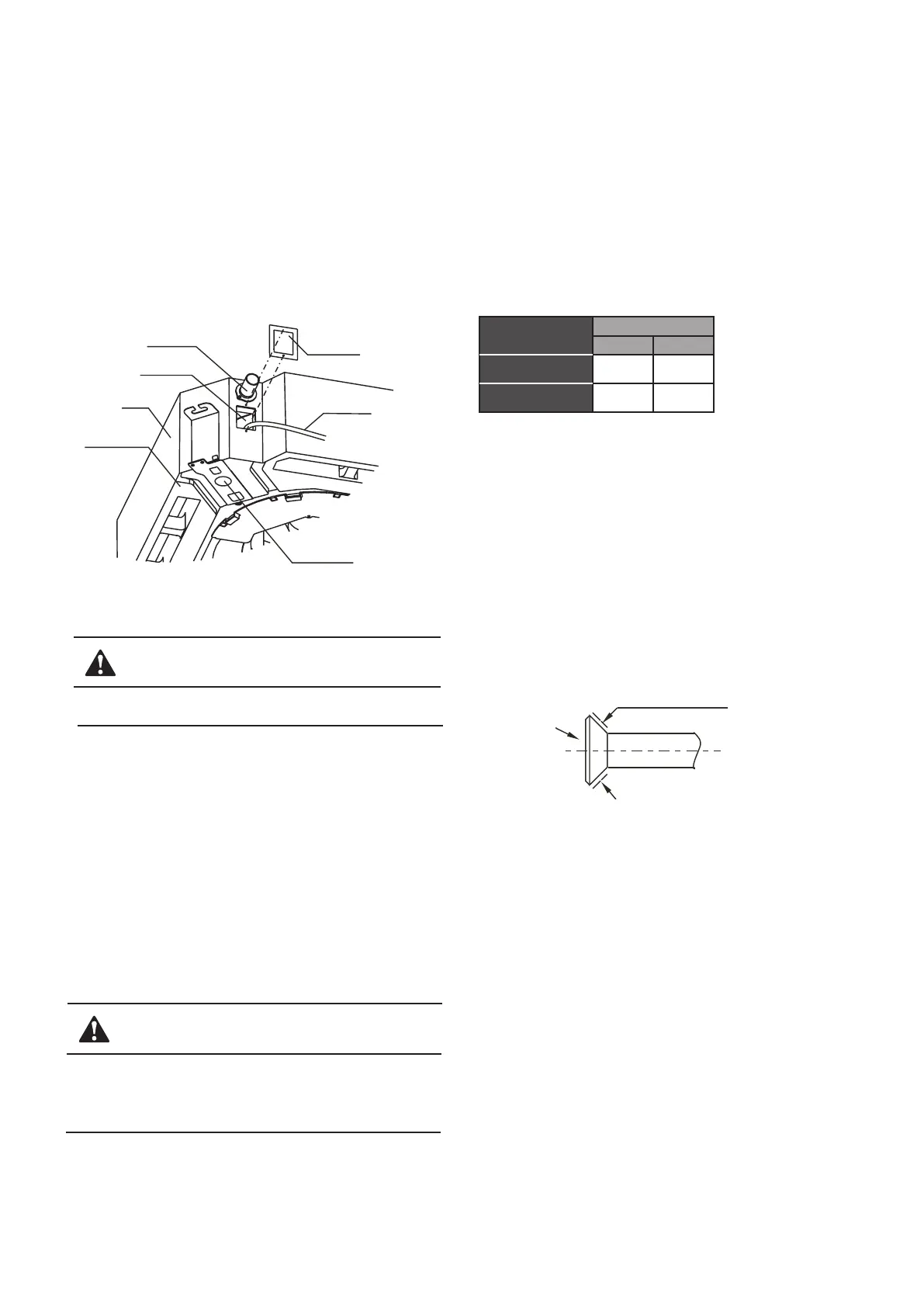
1) Remove the water finding cap, charge 2000 ml water into a
defrosting pan through the water orifice by a water charged pipe.
(See Fig. 5-3)
2) Power on the unit and run cooling mode. Check that the noise of
the water drain pump is normal and that water discharges well.
(Depending on the length of the drainage pipe, it may take about
one minute for water to start draining.) Then, check whether the
joints leak.
CAUTION
Fig. 5-3
Pumping pipe
Water finding orifice
Main body
Defrosting pan
Water finding cap
Water charged pipe
Drain plug
If an error occurs, solve the problem asap.
3) Stop the air conditioner and check for the problem in about 3
minutes. Improperly setting the drainpipe can lead to water
backflow and cause the alarm detector in the control box flash
or water to overflow from the defrosting tray.
4) The alarm will flash if water level exceeds the alarm thresh-
old. Please check whether the drain pump is in water discharge
mode. If the level does not decrease to under the alarm
threshold within 3 minutes, the unit will close down. You must
switch of the power and discharge the accumulated water. Then,
the unit can restart normally.
5) Cut off the power, discharge the accumulated water, and
reset the test cap to its original position.
CAUTION
A drain plug at the bottom of main unit is used for discharging
any accumulated water in the defrosting tray when an error
occurs. During normal operations, ensure that this plug is
inserted tightly to prevent water leaks.
6. INSTALL THE CONNETING PIPE
6.1 The connective length of indoor and outdoor piping
and those height difference requirements.
Connect to different outdoor units with a different connective length
based on height difference requirements. Please refer to Indoor Unit
Installation Manual for details.
6.2 Piping materials and size
1) Piping materials: Copper tube special for air conditioner, normally
T2M.
2) Piping size: Refrigerant is R410A, please refer to Table: 6-1
≤4500W
≥5600W
φ6.4 φ12.7
φ15.9φ9.5
Table: 6-1
Applicable for models that use R410A refrigerant
Indoor unit model
Piping size (mm)
Liquid side
Air side
6.3 Procedure for connecting pipes
1. Measure the required length of the connective pipes and configure
them as per the following procedure. (Refer to the Pipeline Connec-
tion for details)
1) Connect the indoor unit first, and then connect the outdoor unit.
a. The pipe bend should be handled carefully to prevent damaging
the pipe and insulation layer.
b. Before fastening the flared nut, apply refrigerant oil on the outer
surface of the pipeline flare and the taper surface of the connection
nut. Rotate the nut for 3-4 times before fastening it (see Fig.6-1).
Fig.6-1
Apply refrigerant oil
c. When connecting or disconnecting the pipe, use two wrenches at
the same time.
d. Do not rest the weight of the connective pipe on the adapter for
the indoor unit. Excessive load on the adapter of the indoor unit may
deform the pipe and thus affect the cooling/heating effect.
2) The valve of the outdoor unit should be closed completely (as in
factory status). Every time when connecting the pipe, screw the
valve nut, and connect the flared pipe (within 5 minutes). If the nut is
left loose for a long time on the valve, dust and other foreign
substances may enter the pipeline system and lead to fault.
 Loading...