M850-00
T855 Initial Tuning & Adjustment
B3.1
Copyright TEL 31/09/98
3 T855 Initial Tuning & Adjustment
Caution:
This equipment contains CMOS devices which are susceptible to dam-
age from static charges. Refer to Section 1.2 in Part A for more infor-
mation on anti-static procedures when handling these devices.
The following section describes both short and full tuning and adjustment procedures
and provides information on:
• channel programming
• selecting the required audio links
• synthesiser alignment
• receiver front end and IF alignment
• noise and carrier level mute adjustment
• setting the line and monitor output levels
• setting up the RSSI.
Note:
Unless otherwise specified, the term "PGM800Win" used in this and follow-
ing sections refers to version 2.00 and later of the software.
Refer to Figure 4.3 which shows the location of the main tuning and adjustment con-
trols. Refer also to Section 6 where the parts lists, grid reference index and diagrams
will provide detailed information on identifying and locating components and test
points on the main PCB. The parts list and diagrams for the VCO PCB are in Part E.
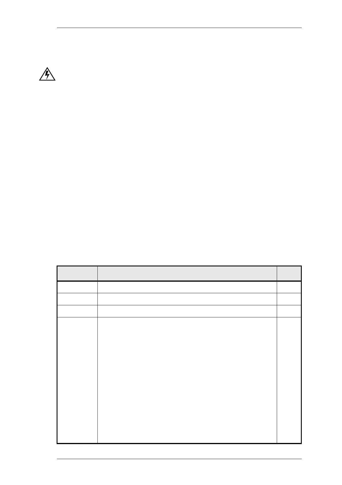
Section Title Page
3.1 Introduction 3.3
3.2 Channel Programming 3.3
3.3 Test Equipment Required 3.4
3.4
3.4.1
3.4.2
3.4.3
3.4.4
3.4.4.1
3.4.4.2
3.4.5
3.4.6
3.4.6.1
3.4.6.2
3.4.6.3
3.4.7
Short Tuning Procedure
Introduction
Synthesiser Alignment
Front End Alignment
Mute Adjustment
Noise Mute
Carrier Level Mute
Line Amplifier Output
CTCSS
Decoder Operation
Opening Sinad
High Pass Filter
RSSI (If Fitted)
3.5
3.5
3.5
3.5
3.6
3.6
3.6
3.6
3.7
3.7
3.7
3.7
3.8
 Loading...


