M850-00
T858/859 Fault Finding
D4.13
Copyright TEL 31/09/98
4.7 Replacing RF Power Transistors
Caution:
Failure to comply with the following procedure can result in failure of
the device due to poor heatsinking, or worse, can endanger the health
of the assembler if the beryllium oxide die carrier is smashed during
assembly.
Caution:
As the location of certain components in the PA is critical to perform-
ance, it is important that any components removed or disturbed are
refitted in
exactly
the same position.
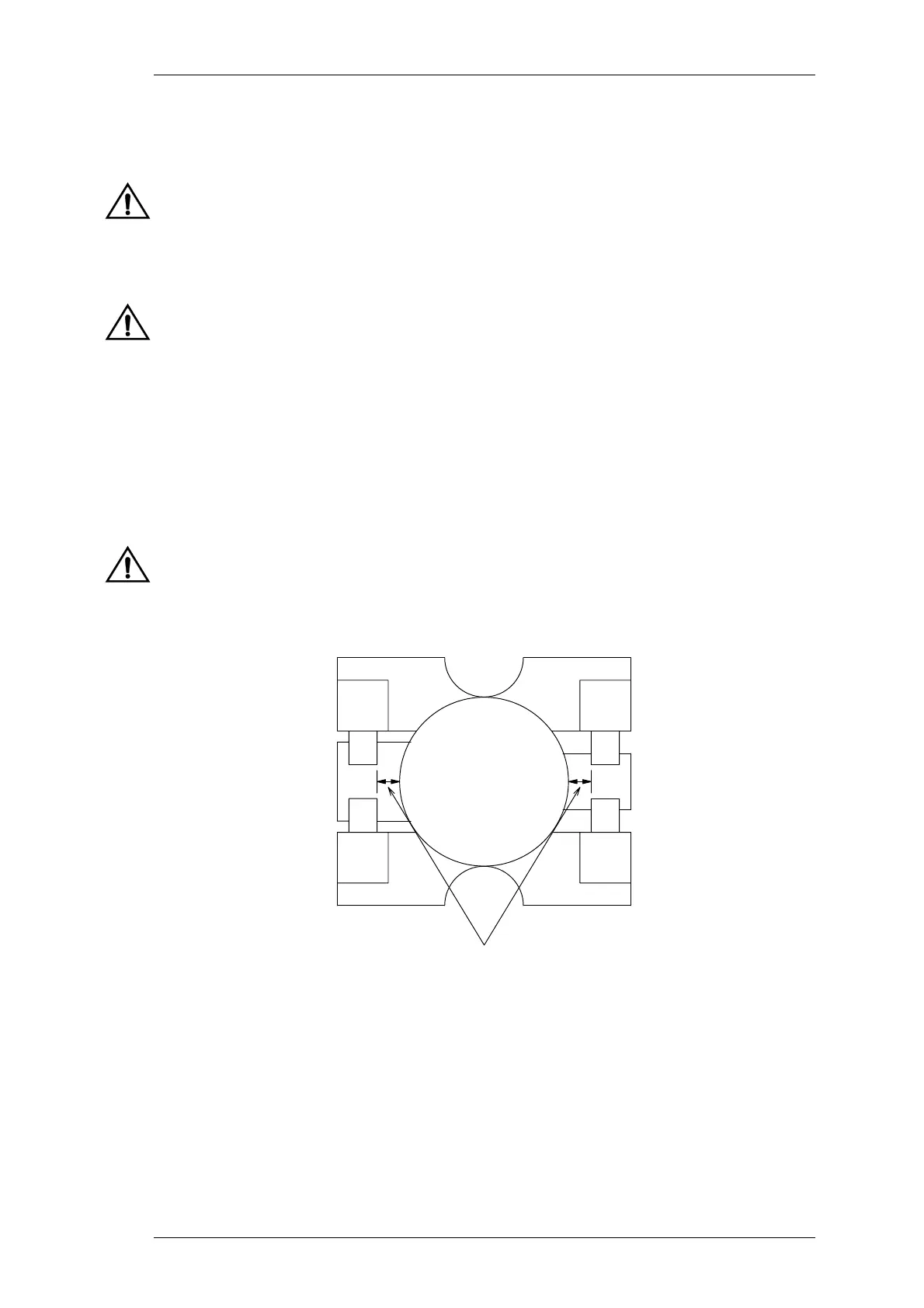
Before attempting to remove a transistor, measure the distance
between the capacitors and transistor body to the nearest 0.5mm (meas-
urement "A" in Figure 4.2) so that the capacitors can be replaced in
exactly
the same position. These measurements are shown in Figure
4.2 for the 6LFL package, however the same procedure applies for the
SOE (stud) package.
Caution:
Do not apply too much heat or pressure to the PCB pads and tracks as
you may damage them or lift them from the PCB, causing permanent
damage to the PA.
Figure 4.2 Typical Transistor/Capacitor Spacing (Not To Scale)
Desolder and remove the components from around the transistor.
Q4/Q6/Q7 Only: Desolder and remove the two solder tags.
Desolder the transistor tabs by heating with a soldering iron and lifting away
from the PCB with a screwdriver or thin stainless steel spike, then remove the
device.
base collector
measurement A
 Loading...


