36 Installing the Radio TM9300/TM9400 Installation Guide
© Tait Limited December 2015
Attempting to replace SMT components without the necessary training,
tools, and equipment can cause permanent damage to the radio.
With the above two options, the radio always stays off when power is first
applied. The radio can only be turned on with the on/off button.
Ignition Signal The ignition signal can be used to power up and power down the radio.
This will turn the radio off when the ignition key is off to avoid flattening
the battery, and will turn the radio on or return to its previous state (as
programmed) when the ignition key is on.
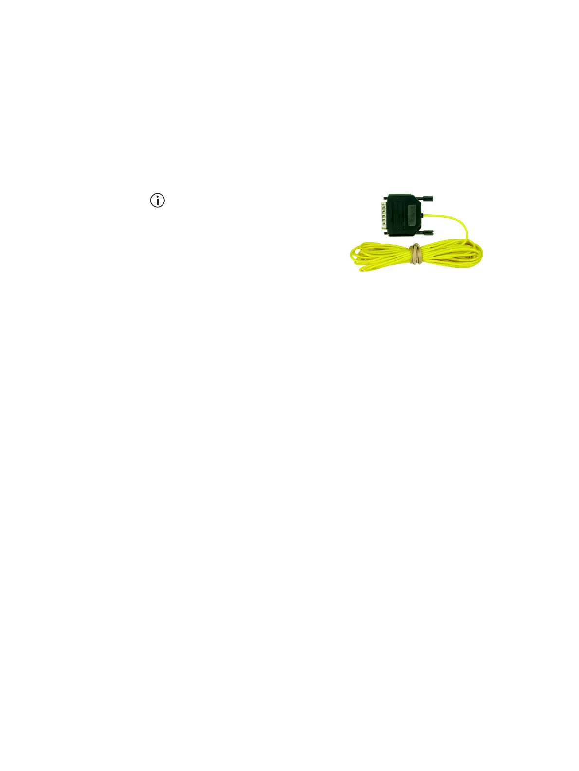
A TMAA04-05 ignition sense kit is
available. The kit comprises a mating
plug for the radio’s auxiliary connec-
tor and a 13 foot (4m) length of cable
to connect to the vehicle’s
ignition signal. Refer to the installa-
tion instructions supplied in the kit for
full details.
Notice The AUX GPI3 line must be programmed to ‘Power Sense
(Ignition)’ and active to ‘High’. For more information, refer to the
online help of the programming application.
■ Connect the ignition signal to pin 4 (AUX GPI3) of the auxiliary
connector.
Notice The logic thresholds for AUX GPI3 are based on 3V3 levels.
However, AUX GPI3 can be connected directly to a +13.8V
ignition signal (for input levels, refer to Table 4.3 on page 35).
Emergency Switch The radio allows for connection of an emergency switch to any input line
to enter the emergency mode. If connected to the AUX GPI2 input line, the
radio can also use ‘emergency power sense’ to power up the radio to enter
the emergency mode.
The selected input line must be programmed to ‘Enter Emergency Mode’
and active to ‘Low’. To use ‘emergency power sense’, hardware link
LK3M must be fitted (factory default), and AUX GPI2 must be used.
For more information, refer to “Power Sense Options” on page 19 and the
online help of the programming application.
■ Connect a normally open switch between the pin of the input line (pin 5
for AUX GPI2) and pin 15 (AGND) of the auxiliary connector.
 Loading...


