Cable Connections
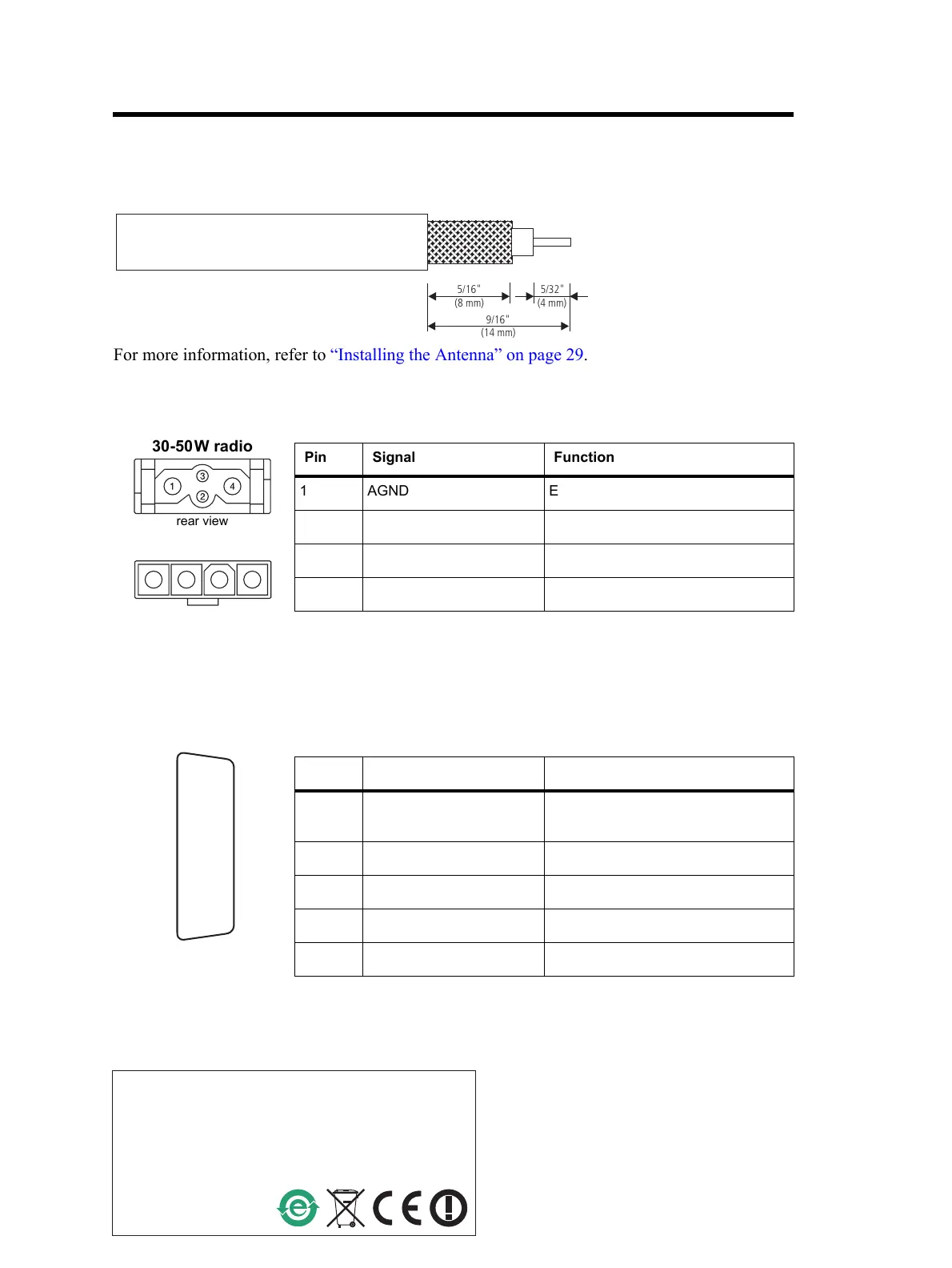
Terminating the Antenna Cable
Power and Remote Speaker Connections
For more information, refer to “Connecting the Power Cable to the Power Source” on page 30 and
“Connecting an External Speaker” on page 33.
Ignition Sense, Emergency Switch, and External Alert Device Connections
For more information, refer to “Connecting to the Auxiliary Connector (Ignition Signal,
Emergency Switch, External Alert Devices)” on page 33.
5/16"
9/16"
5/32"
(4 mm)
(8 mm)
(14 mm)
For more information, refer to “Installing the Antenna” on page 29.
rear view
30-50W radio
Pin Signal Function
1 AGND Earth return
2 SPK– External speaker –
3 SPK+ External speaker +
4 +13V8 BATT DC power input (10.8V to 16.0V)
1 2 3 4
rear view
25W radio
rear view
J
B
C
D
E
F
G
H
I
1)
1!
1@
1#
1$
1%
Pin Signal Function
4 AUX GPI3 Ignition sense (see “Ignition Signal”
on page 36)
5 AUX GPI2 Emergency switch +
8 +13V8 SW External alert device +
10 AUX GPIO4 External alert device –
15 AGND Emergency switch –
 Loading...


