12_ TECHNICAL MENU
The control unit is supplied with standard factory settings, suitable
to move most doors commercially available, in compliance with
European standards.
However a series of parameters may be modied, by means of
dipswitches 7-8 and trimmers TRM4, TRM5 and TRM6.
The function of these trimmers varies according to the position of
dipswitches 7-8, as specied in the table below.
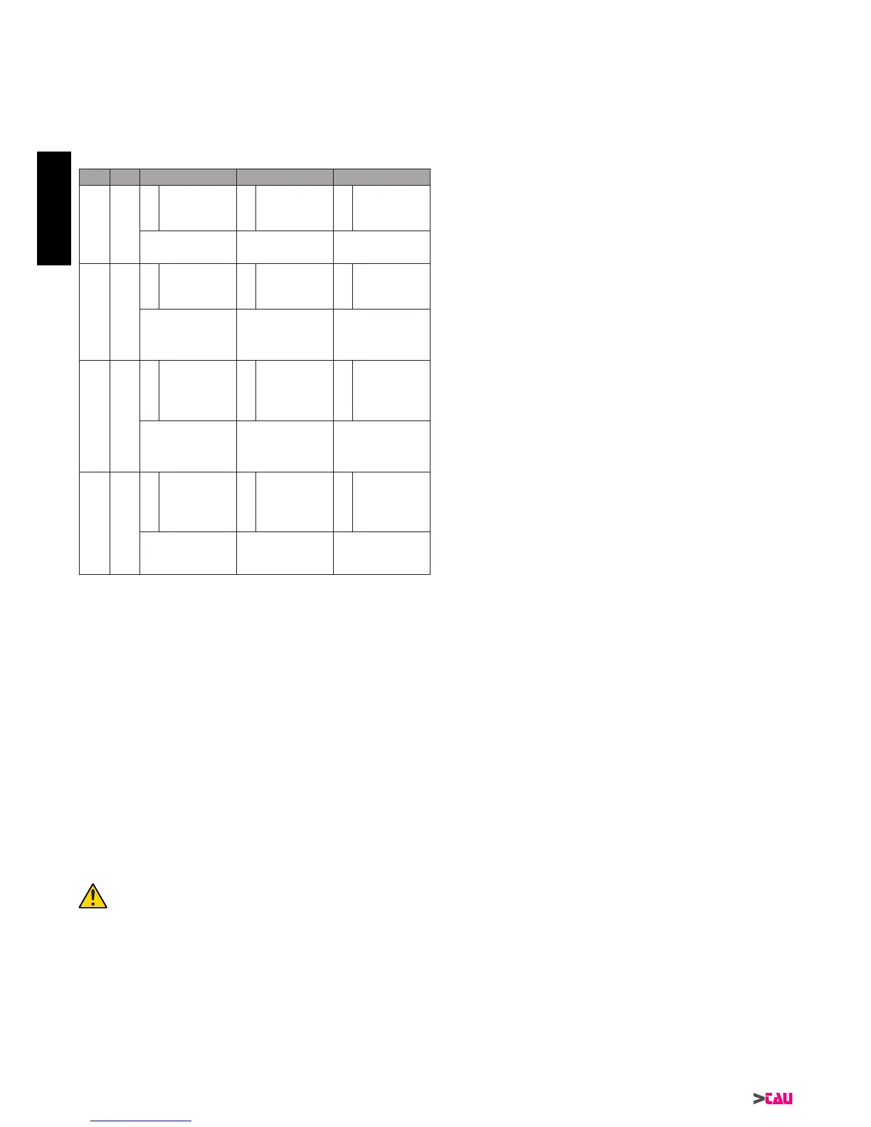
Dip7 Dip8 TRM4 TRM5 TRM6
OFF OFF
1
Set to decel-
eration on
opening
2
Set to de-
celerationon
closing
3
Minimum
speed(Vmin)
Turn clockwise for the
door to start deceleration
earlier
Turn clockwise for the
door to start deceleration
earlier
Turn clockwise for high
speed at the end of de-
celeration
OFF ON
4
Opening
speed (Vap)
5
Closing
speed (Vch)
6
Thrust on
closinglimit
position
Turn clockwise to in-
crease speed
Turn clockwise to in-
crease speed
At the end of closing the
motor pushes against the
limiter for a brief interval.
Turn clockwise to in-
crease time interval
ON OFF
7
Opening ac-
celeration
ramp
8
Closing ac-
celeration
ramp
9
Encoder
engagement
time (motor
start)
Turn clockwise to in-
crease time of accelera-
tion ramp
Turn clockwise to in-
crease time of accelera-
tion ramp
Turn clockwise to in-
crease the start-up time in
which the encoder signal
is ignored (no obstacles
are detected)
ON ON
10
Limit switch
position
onopening
(FCA)
11
Obstacle
detectionlimit
position on
closing
1
12
Belt loosen-
ing
Turn clockwise to in-
crease the stopping
distance from opening
limit switch
Turn clockwise to
increase the zone con-
sidered as closing limit
position.
Turn clockwise to in-
crease return to opening
at the end of closing, to
loosen the chain/belt.
Notes:
(
1
) if this parameter is modied, i.e. if the stopping distance
from the mechanical limiter is moved +/- forward, the value
”Opening limit position” (10) must be adjusted to guarantee
the space required to complete a complete manoeuvre.
Recommended procedure for adjustment:
1_ position dipswitches 7 and 8 on the combination re-
quired to modify the specic parameter;
2_ set ALL THREE trimmers to mid-way.
3_ press ENTER to conrm the parameters;
4_ perform a complete open/close manoeuvre and check
that the response is correct.
5_ adjust the trimmers;
6_ press ENTER;
7_ proceed as per point 4 to obtain the required response.
N.B. it is not possible to modify one parameter only. All
three parameters of the selected combination need to
be adjusted each time.
To restore the standard conguration to the control
unit (factory settings), press and hold ENTER for at le-
ast 5 sec.
13_ MALFUNCTIONS: TROUBLESHOOTING
The automation does not start
a_ Use a Multimeter to check presence of 230 Vac supply volt-
age.
b_ Check that the NC contacts of the card are effectively nor-
mally closed (3 green leds lit) and that the red leds for open-
ing commands are off.
c_ Set dipswitch 6 (fototest) to OFF;
d_ Set trimmers FRC and FRA to the maximum value;
e_ Use the Multimeter to check that the fuses are intact.
The radio control range is low
a_ Check that the earth connection and aerial signal have not
been inverted;
b_ Do not make joints to extend the aerial cable;
c_ Do not install the aerial at low heights or concealed by walls
or columns;
d_ Check status of the radio control batteries.
The door opens in the opposite direction
a_ Invert the motor connection (RED and BLACK wires on the
motor).
ENGLISH
 Loading...